SD/SDV-Series Safety Features
Spin Robotics Safety Shield
The SD/SDV-Series screwdriver tool is designed such that the screw and bit are covered by the Spin Robotics safety shield during operation.
This reduces the risk of contact with rotating or sharp elements.
Note
As specified in the technical datasheet (Chapter 2), the maximum screw length within the safety shield is 35 mm.
The screw length must be configured in the SpinInterface. See Section 7.4 and Section 5.5.4 (URCap / Screw Feeder).
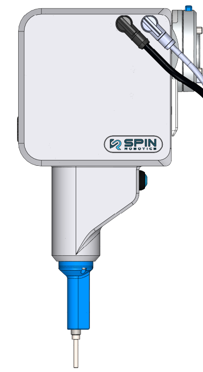
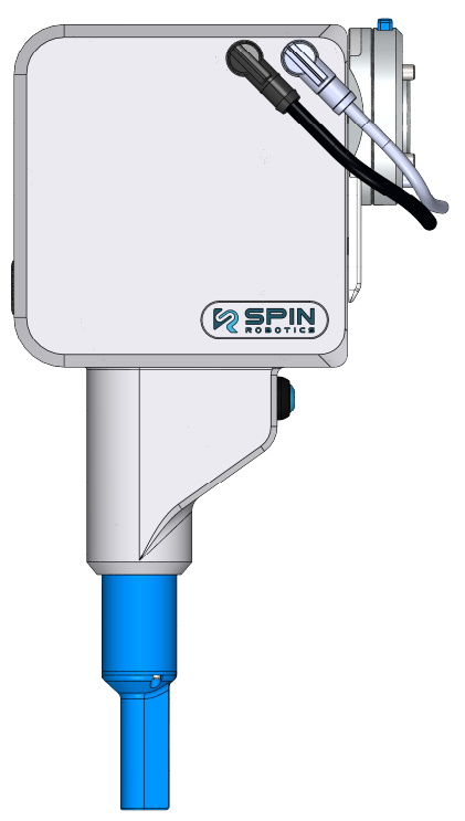
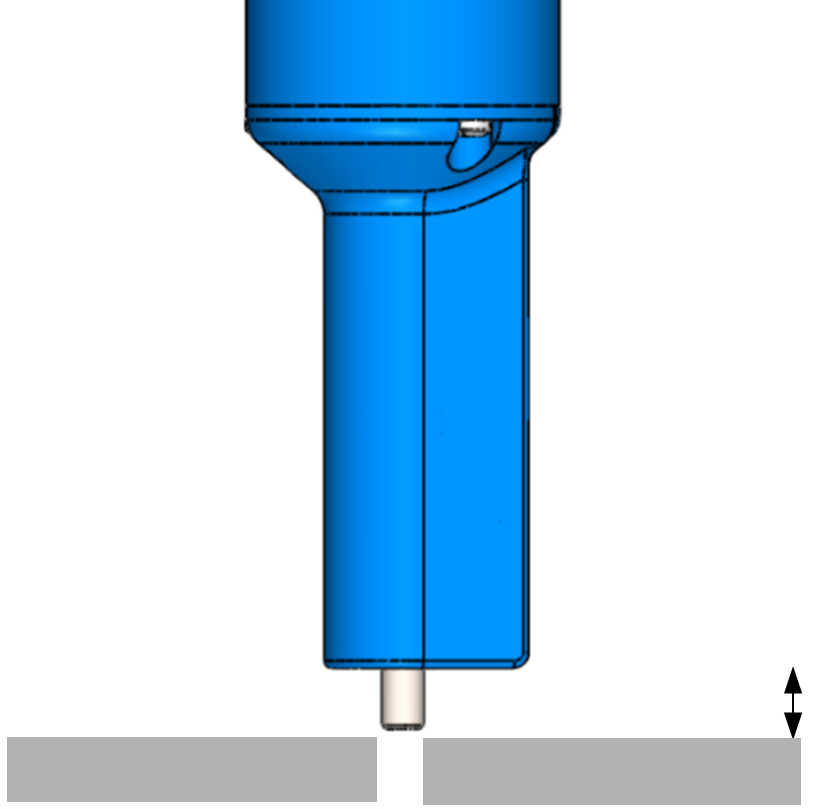
The safety shield retracts at approximately 6 mm above the surface during screw insertion.
Since fingers and hands are typically thicker than 6 mm, this reduces the risk of crushing injuries during normal operation.
Warning
The safety shield retraction distance (S1) shall NOT exceed 6 mm.
Increasing this distance may introduce a crushing hazard.
48V Motor Supply
The SD/SDV-Series tool is powered by a 48V motor supply routed through the SpinBridge.
On delivery, the 48V circuit is closed by a factory-installed jumper on the front of the SpinBridge.
This connection point allows integration of an external safety device, such as a safety relay.
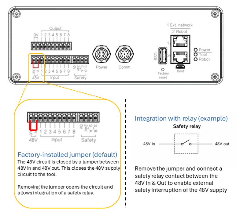
Factory-installed jumper and example of safety relay integration for interruption of the 48V motor supply.
When using robot-integrated control (e.g. URCap or Kassow Cbun), the SpinBridge automatically disables the 48V supply in case of an emergency stop.
When using I/O control, the integrator shall ensure that the 48V motor supply is disabled when an emergency stop is triggered.
By replacing the jumper with a safety relay contact, the 48V supply can be interrupted as part of the safety system.
Important
The 48V motor shutdown via robot-integrated control is not a safety-rated function.
For applications requiring a higher level of safety, it is recommended to interrupt the 48V supply using a safety relay.
The necessity of this function shall be determined by the risk assessment.
Note
This function provides an additional layer of safety by removing power to the tool, independent of robot motion control.
Warning
If this function is used, the safety relay and wiring must be implemented and validated by the integrator in accordance with applicable safety standards.
Important
Failure to remove motor power during an emergency stop may result in unsafe behavior.
See the Dashboard manual for details on I/O control.
Safety Sensor
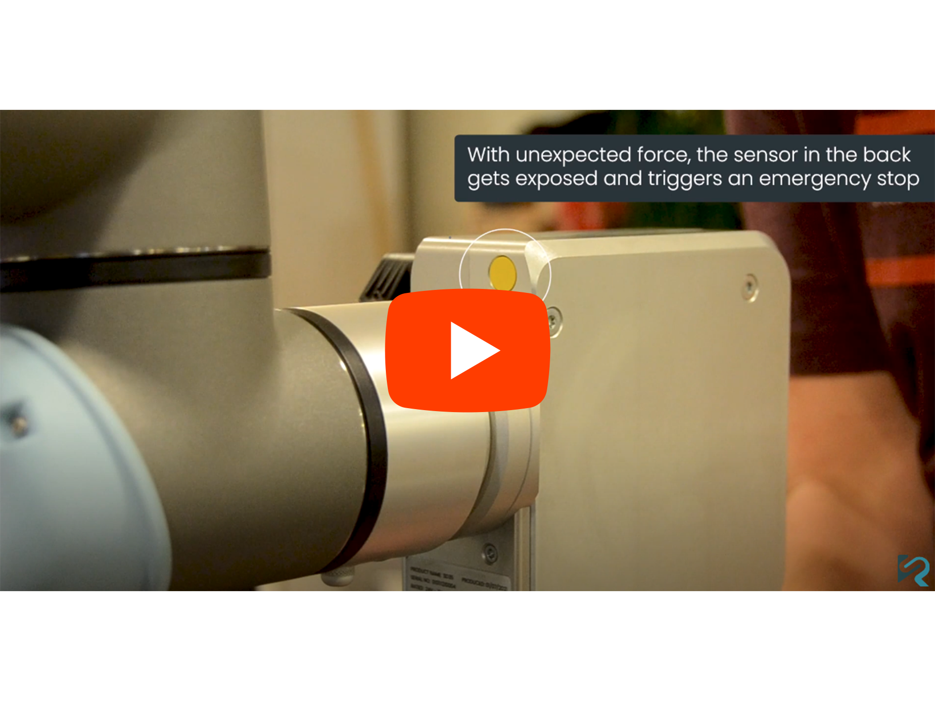
The SD/SDV-Series includes a built-in safety sensor with Performance Level D.
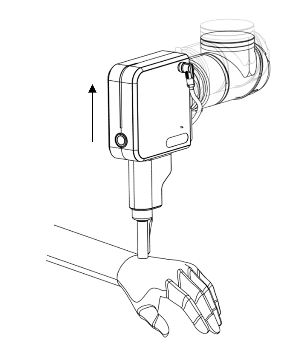
The sensor detects unexpected contact forces in the vertical direction.
Trigger threshold: ≥ 45 N
Activation: during approach to screw position
The safety system is based on a mechanical compliance mechanism:
The tool is mounted on a linear rail system
External force causes the tool to move upwards
If displacement exceeds 10 mm:
Robot motion is stopped
Tool operation is disabled
Important
The safety sensor is part of the overall safety chain and must be correctly connected to the robot safety system.
Warning
The SD/SDV-Series shall NOT be used in collaborative applications without connecting the safety cable between the SpinBridge and the robot controller.
Programming Safe Robot Trajectories
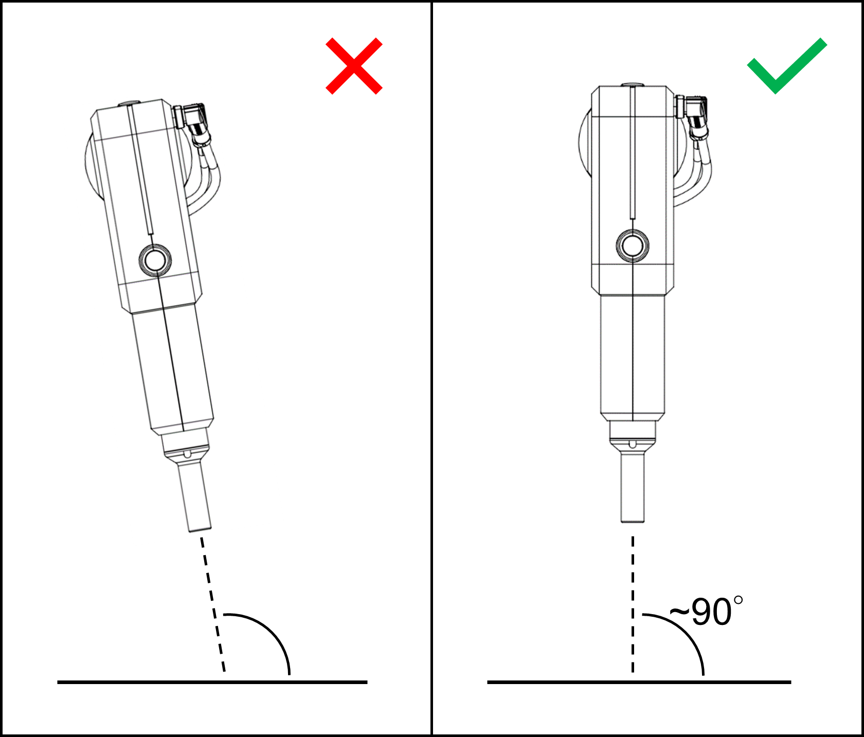
To reduce impact forces during potential contact, robot trajectories shall be programmed to approach the screw position perpendicularly (90°).
This ensures:
Maximum contact area of the safety shield
Reduced pressure and peak forces
Improved compliance with safety limits
Note
Safe trajectory planning is essential to comply with force limits defined in:
ISO 10218-2:2025
ISO/TS 15066
Improper approach angles may increase local pressure and injury risk.
See the Dashboard manual for programming details.