Risk Assessment
The integrator must perform a risk assessment of the complete robot application in accordance with ISO 12100.
Important
The SD/SDV tool is a component and does NOT ensure safety on its own.
Safe operation depends on correct system integration.
Risk Assessment Approach
A complete risk assessment must consider:
Intended use of the system
Foreseeable misuse
All phases of operation (installation, operation, maintenance, fault handling)
Interaction between robot, tool, workpiece, and operator
Important
The risk assessment must be documented and included in the technical file of the complete machine or system.
Note
Risk reduction shall follow an iterative process of: risk identification, risk evaluation, and implementation of protective measures.
Tool Safety Features
The SD/SDV-Series includes features supporting safe integration:
Smooth and rounded design (reduced injury risk)
Linear compliance and built-in safety sensor
Safety shield covering rotating bit and screw
Light and sound signals indicating tool operation
Note
These features reduce risk but do NOT eliminate the need for system-level safety.
Identified Hazards
The following hazards must be addressed during system design:
Collision between robot, tool, and human
Crushing or trapping between robot and surroundings
Contact with rotating bit or screw
Incorrect screw insertion causing unexpected movement
Cable entanglement with personnel or equipment
Loose components (e.g. screws or mounting)
Mandatory Safety Measures (Shall Requirements)
The following shall be verified before operation:
SpinMount is correctly installed using dowel pin and M6 screws
Safety cable is correctly connected to the robot emergency stop circuit
No electrical modifications are made
Cables are properly secured to the robot
For collaborative applications:
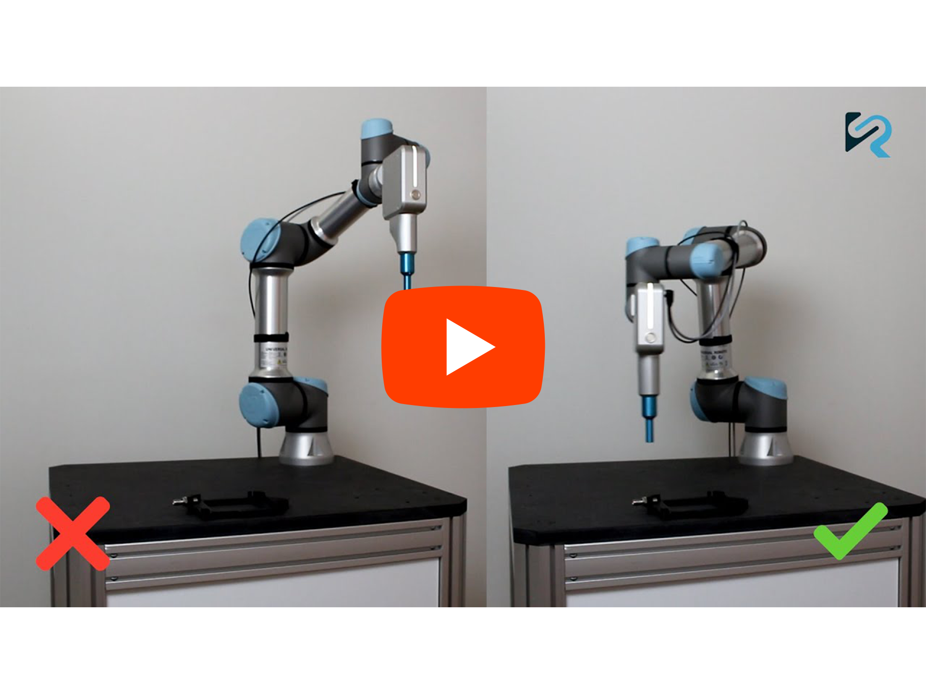
Robot speed ≤ 250 mm/s when approaching screw position
Screwdriving starts ≤ 6 mm from surface
Tool approaches perpendicular (90°)
Tool path does not move near head level
Safety shield is installed and functioning
Safety shield covers the screw during motion
Stopping Performance and Force Validation
The stopping performance of a robot system has a significant influence on the resulting contact forces during unintended collisions.
Different robots and collaborative robots may have substantially different:
Stopping times
Deceleration profiles
Mechanical stiffness and inertia
This applies to both:
Emergency stop (Category 0 or Category 1 stop depending on system design)
Safeguard / protective stop (typically Category 2 stop)
Important
The resulting impact forces are highly dependent on the robot type, payload, speed, and stop performance.
Understanding Contact Forces
To evaluate safety in collaborative robot applications, it is important to understand how contact forces behave under different conditions.
Two types of contact are particularly relevant:
Transient (impact) contact Occurs during short-duration events when the robot stops or changes direction
Quasi-static (sustained) contact Occurs when a body part is trapped and force is applied over time
The following figures illustrate how these two contact types behave as a function of robot speed, robot size, and how the integrated safety sensor influences the resulting forces.
Important
Contact forces cannot be directly observed during operation and must therefore be understood through measurement and analysis.
The following figures provide a visual representation of how contact forces typically behave under different conditions.
Note
The figures are intended to provide a general understanding of force behavior. They are not specific to a single robot model or application.
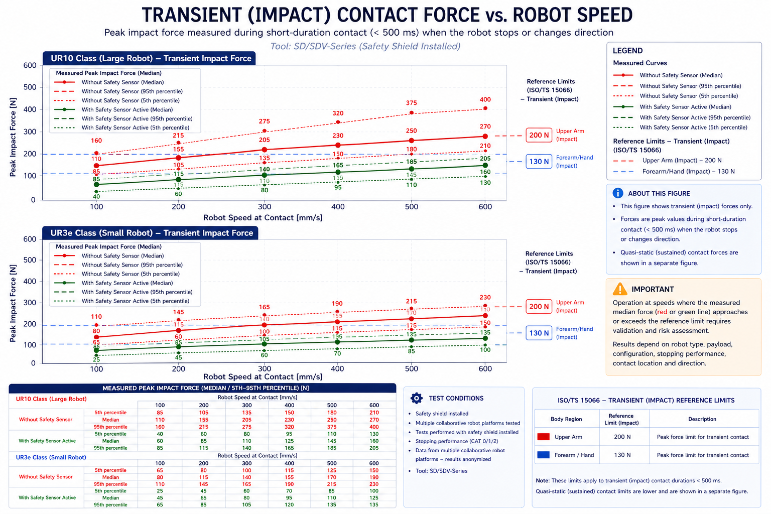
Transient (impact) contact force as a function of robot speed. These forces occur during short-duration contact (< 500 ms), for example when the robot stops or changes direction.
The curves represent measured peak forces. The integrated safety sensor reduces peak forces and improves compliance with collaborative safety limits.
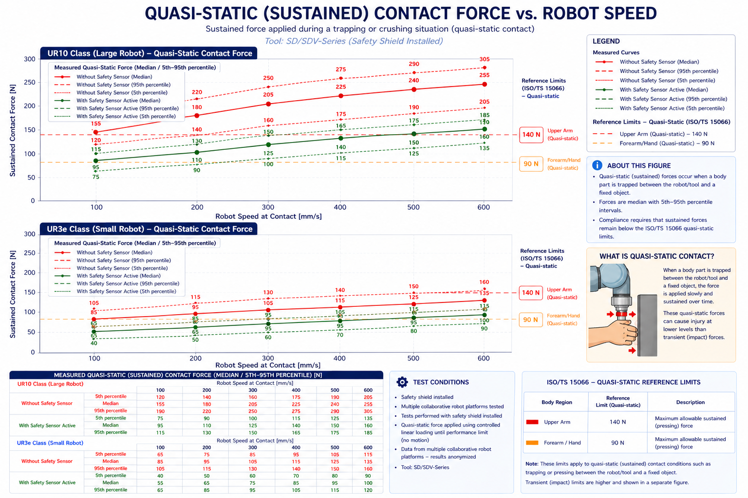
Quasi-static (sustained) contact force during a trapping or crushing situation.
In these situations, a body part may be pressed between the robot/tool and a fixed object, resulting in sustained force over time.
Quasi-static forces are typically more critical than transient forces, as they can cause injury at lower force levels.
Note
The integrated safety sensor primarily reduces transient (impact) forces, while quasi-static risks must be addressed through system design and proper risk assessment.
Transient vs. Quasi-static Contact
Important
It is essential to distinguish between transient and quasi-static contact:
Transient (impact): Short-duration contact where the robot is decelerating or changing direction. The force is brief and depends on speed and stopping performance.
Quasi-static (crushing): Sustained contact where a body part is trapped. The force is applied over time and depends on system stiffness and control behavior.
Warning
Quasi-static contact is generally more hazardous than transient impact, even at lower force levels.
Practical Implications
Important
Safe operation cannot be determined from robot speed alone.
The same speed may be safe in one application and unsafe in another, depending on robot type, payload, and stopping performance.
Note
In practice:
Reducing robot speed lowers both impact and quasi-static forces
Larger robots require more conservative limits
Safety functions (e.g. integrated sensors) reduce peak forces
Avoiding trapping situations is critical for safety
Data Interpretation and Limitations
Warning
The figures shown are based on generalized and anonymized test data and are provided for illustrative purposes only.
They must NOT be used as acceptance criteria or proof of compliance.
Note
Actual forces depend on multiple factors, including:
Robot type and size
Payload and tool configuration
Robot speed and trajectory
Stopping performance
Contact location and direction
Application-specific conditions
Significant variation between robot platforms can occur.
Important
Compliance with applicable force and pressure limits must always be verified for the specific application through risk assessment and, where necessary, measurement.
Typical Observed Force Ranges (Impact)
Robot class |
Without safety sensor |
With safety sensor |
|---|---|---|
Small (UR3e) |
~80 – 200 N |
~50 – 140 N |
Large (UR10) |
~150 – 270 N |
~100 – 160 N |
Note
Test results show a clear difference between smaller and larger robot platforms.
Smaller robots (e.g. UR3e class):
Lower mass and stiffness
Lower resulting impact forces
Wider margin to collaborative limits
Larger robots (e.g. UR10e class):
Higher mass and inertia
Higher peak impact forces at the same speed
Greater dependency on stopping performance and system configuration
Important
The same robot speed may result in significantly different impact forces depending on robot size and characteristics.
Larger robots require more careful validation of force limits.
Force and Pressure Limits
For collaborative applications, force and pressure limits must comply with:
ISO 10218-2:2025
ISO/TS 15066 (biomechanical limits for human contact)
These include:
Transient contact limits (dynamic impact)
Quasi-static contact limits (crushing situations)
Note
Quasi-static contact occurs when a body part is trapped between the robot/tool and a fixed object and may result in sustained forces.
Validation by Measurement
Due to variations between robot systems, it may be necessary to perform force and pressure measurements as part of the risk assessment.
Important
If compliance with force limits cannot be demonstrated by design, validation by measurement shall be carried out.
Typical scenarios include:
High robot speeds
High payload or stiff robot structures
Application-dependent stop performance
Potential trapping or clamping situations
Worst-case conditions shall be considered (e.g. maximum speed, payload, and reach)
Integrator Responsibility
The integrator shall ensure that:
All relevant risks are identified and mitigated
Applicable standards are followed
Validation results are documented
Reference Testing (Observed Behaviour)
Internal testing across multiple collaborative robot platforms shows:
Significant variation in measured forces between robot models
Increased forces with higher robot speeds
Lower forces when integrated safety functions are active
Strong dependency on stopping performance and system configuration
Note
The values below are indicative ranges observed under controlled conditions. Actual results will vary depending on robot, payload, and application.
Condition |
Transient force (approx.) |
Quasi-static force (approx.) |
|---|---|---|
Low speed (~250 mm/s) |
100 – 150 N |
120 – 180 N |
Medium speed |
150 – 250 N |
180 – 300 N |
High speed (>350 mm/s) |
250 – 400 N |
300 – 500 N |
Warning
These values are indicative only and must NOT be used as acceptance criteria.
Compliance with applicable force and pressure limits must be verified for each specific application.
Validation and Testing
Before operation, the complete system must be validated:
Verify all safety functions
Test emergency stop response
Confirm safe robot behavior in all modes
Collaborative Operation
The SD/SDV tool has been evaluated in accordance with:
ISO 10218-2:2025
ISO/TS 15066
Important
The maximum recommended robot speed is 250 mm/s when approaching the screw position.
Additional Resources
Further guidance is available: