Connecting Safety to Robot or PLC
The safety output from the SpinBridge must be connected to a safety input of the robot or PLC (e.g. emergency stop or safeguard stop circuit).
Important
The SpinBridge provides safety output as OSSD signals.
These signals are designed to initiate a safe stop of the robot when the tool safety system is triggered.
The OSSD signals are dual-channel safety outputs designed for Category 3 / Performance Level d (PL d) safety systems.
Safety Signal Overview
The safety system operates as follows:
The tool detects unexpected contact (safety sensor)
The SpinBridge outputs a safety signal (OSSD)
The robot or PLC must initiate a safe stop
Note
The connected system must be able to receive and react to OSSD safety signals.
The safety system is illustrated in the figure below.
It shows how the safety signal is transmitted from the tool, through the SpinBridge, to the robot controller, and how the power supply is provided from the robot to the safety system.
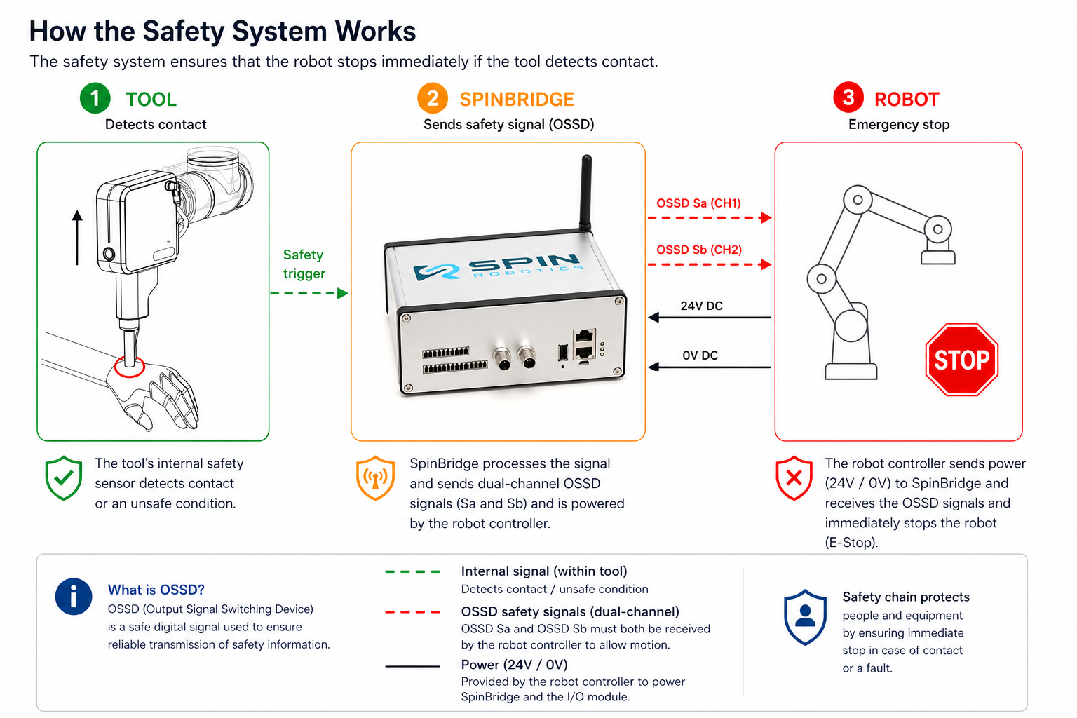
Safety signal flow from tool to robot controller.
The tool detects contact and triggers the safety system. The SpinBridge transmits dual-channel OSSD signals (Sa and Sb) to the connected controller, which must initiate a safe stop.
The robot controller provides 24V and 0V supply to the SpinBridge.
Note
Both OSSD channels (Sa and Sb) must be active (high) to allow robot operation.
The dual-channel design provides redundancy and fault detection.
If either channel is interrupted or goes low, the controller must perform a safe stop.
Warning
If the safety cable is not correctly connected, the safety function will not operate.
The system must NOT be used in collaborative applications without a functioning safety connection.
Electrical Requirements
Important
The SpinBridge and the robot/PLC MUST share the same electrical reference.
This means:
24V and 0V from the safety cable must be connected
The safety input circuit must use the same voltage potential
Warning
If 24V and 0V are NOT shared:
Safety signals may not be detected
The system may behave unpredictably
Safety function may fail
Note
The shared 24V / 0V reference is required for both safety signal integrity and I/O communication.
Connection Principles
Two typical connection methods are used:
1. Direct OSSD connection (recommended)
Connect OSSD outputs from SpinBridge directly to robot/PLC safety inputs
Requires support for OSSD signals
2. Safety relay (if OSSD not supported)
Use a safety relay to convert OSSD signals
Relay output connects to robot/PLC E-stop circuit
Note
Always verify compatibility with your robot or PLC safety input specifications.
Example: Universal Robots
Connect safety cable to SpinBridge safety input
Connect OSSD outputs to robot safety input (E-stop or safeguard input)
Connect 24V and 0V to robot power supply
Note
Universal Robots support OSSD signals directly.
Example: Kassow Robots
A safety relay is required to interface the OSSD signals with the robot safety inputs.
Important
Kassow robots do NOT support OSSD signals directly.

The safety relay converts OSSD signals from SpinBridge.
Connect safety cable to SpinBridge
Connect OSSD outputs to safety relay
Connect relay outputs to robot emergency stop
Connect 24V and 0V to robot power supply
Verification
After connecting the safety system:
Power on the system
Trigger the safety sensor (e.g. push the tool upwards)
Confirm that the robot stops immediately
Warning
If the robot does NOT stop:
Do NOT operate the system
Check wiring and safety configuration
Common Mistakes
Warning
Most common safety issues:
Missing shared 24V/0V reference
Incorrect wiring of OSSD signals
Robot not configured for safety input
Missing safety relay (non-OSSD systems)
Tip
Always test the safety function before operation.