How to Install
Unpack the system and ensure all components are present before starting.
Follow the steps below in order.
Step 1: Mount SpinMount on Robot
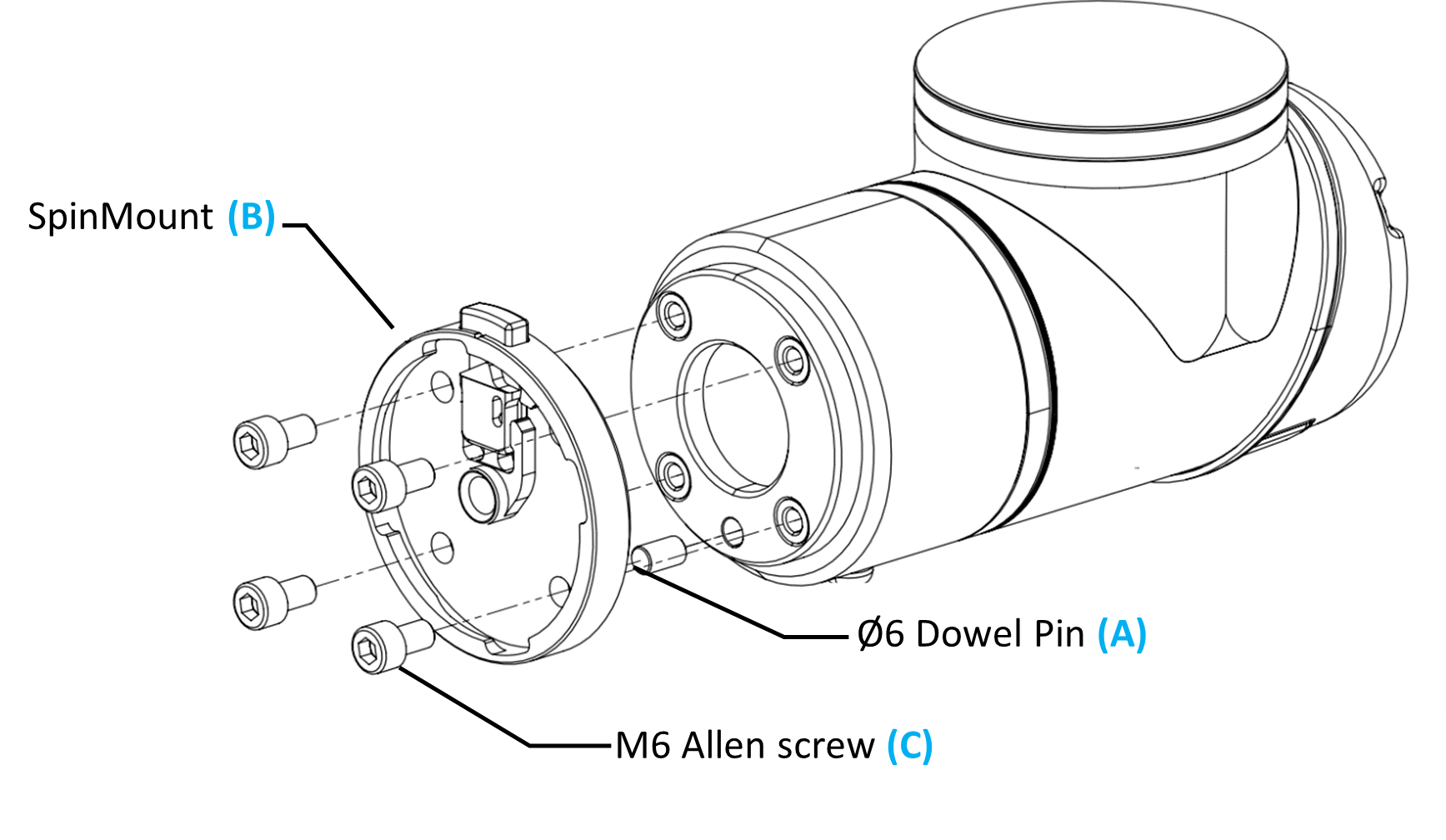
Insert dowel pin (A) into the robot flange
Mount SpinMount (B) using M6 screws (C)
Tighten screws to 8 Nm
Warning
Always use the dowel pin.
If not used:
Tool orientation will be incorrect
Preconfigured TCP will not match
Errors will appear later during programming
Step 2: Mount the Tool
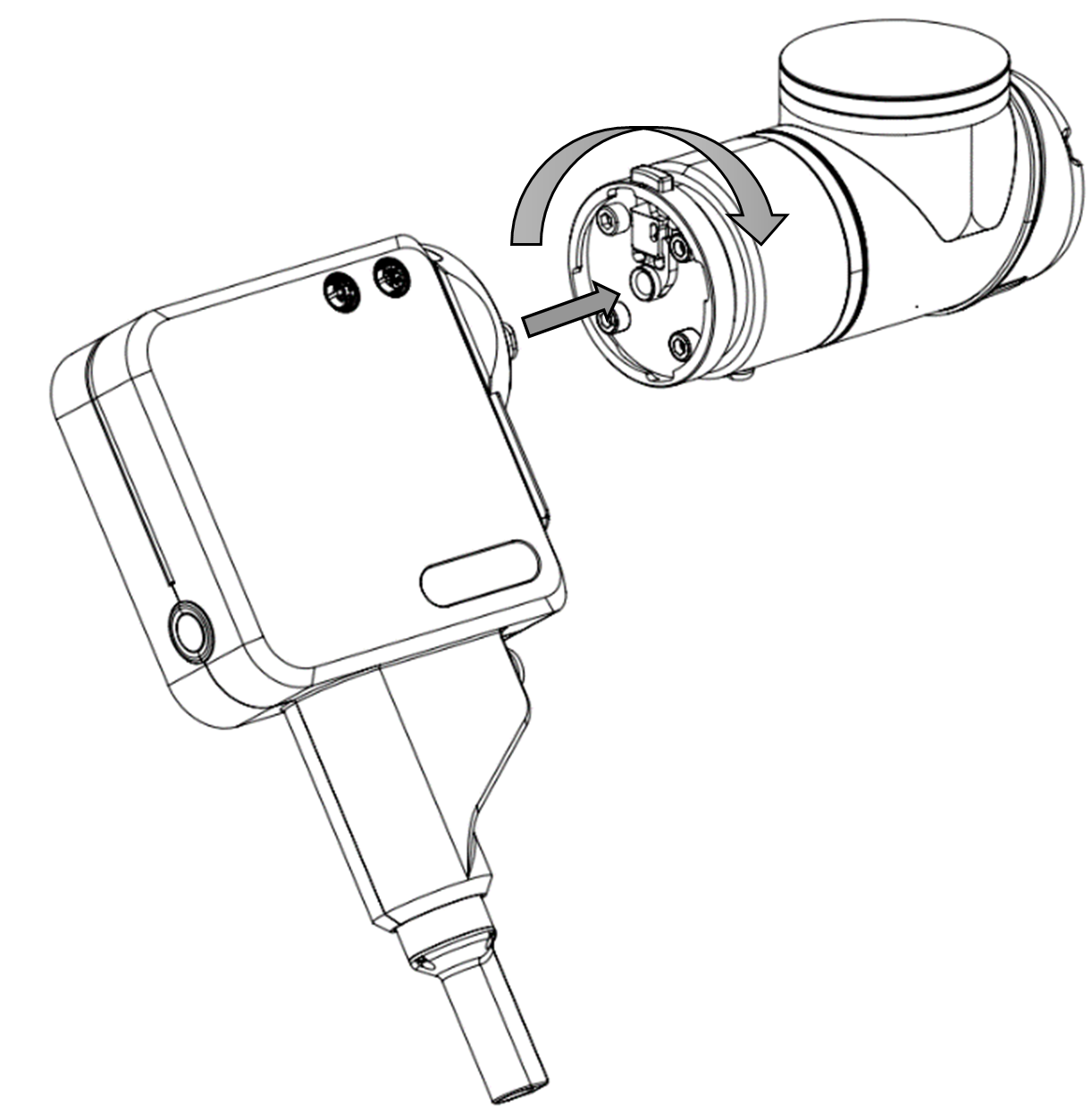
Insert the SD/SDV tool into the SpinMount
Push and rotate clockwise until you hear a “click”
Note
Make sure the tool is fully locked. A loose tool will cause unstable screwdriving.
Step 3: Connect Tool Cables
Connect M12 power cable (D) to the front port
Connect M12 signal cable (E) to the rear port
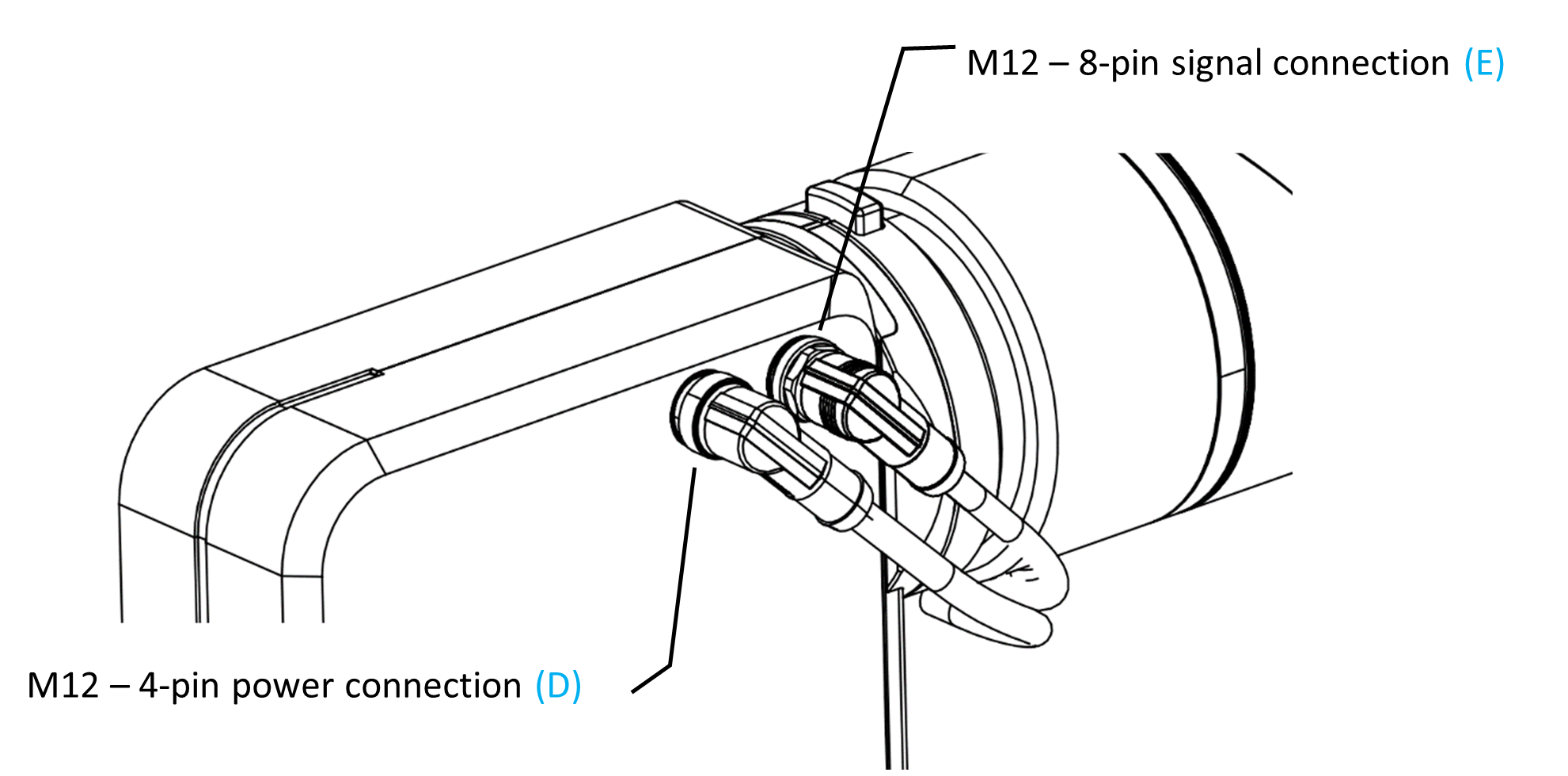
Secure cables using Velcro straps
Ensure sufficient slack at robot joints
Warning
Do NOT tighten cables too tightly.
This may damage cables during robot movement.
Tip
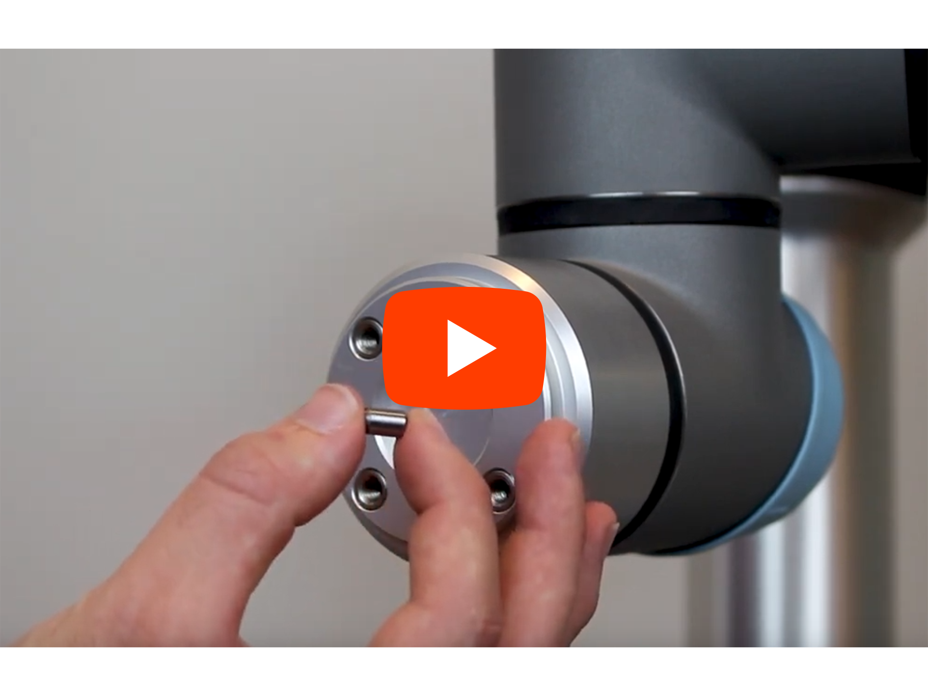
Watch the mounting process:
Step 4: Connect SpinBridge
Connect cables from the tool to the SpinBridge:
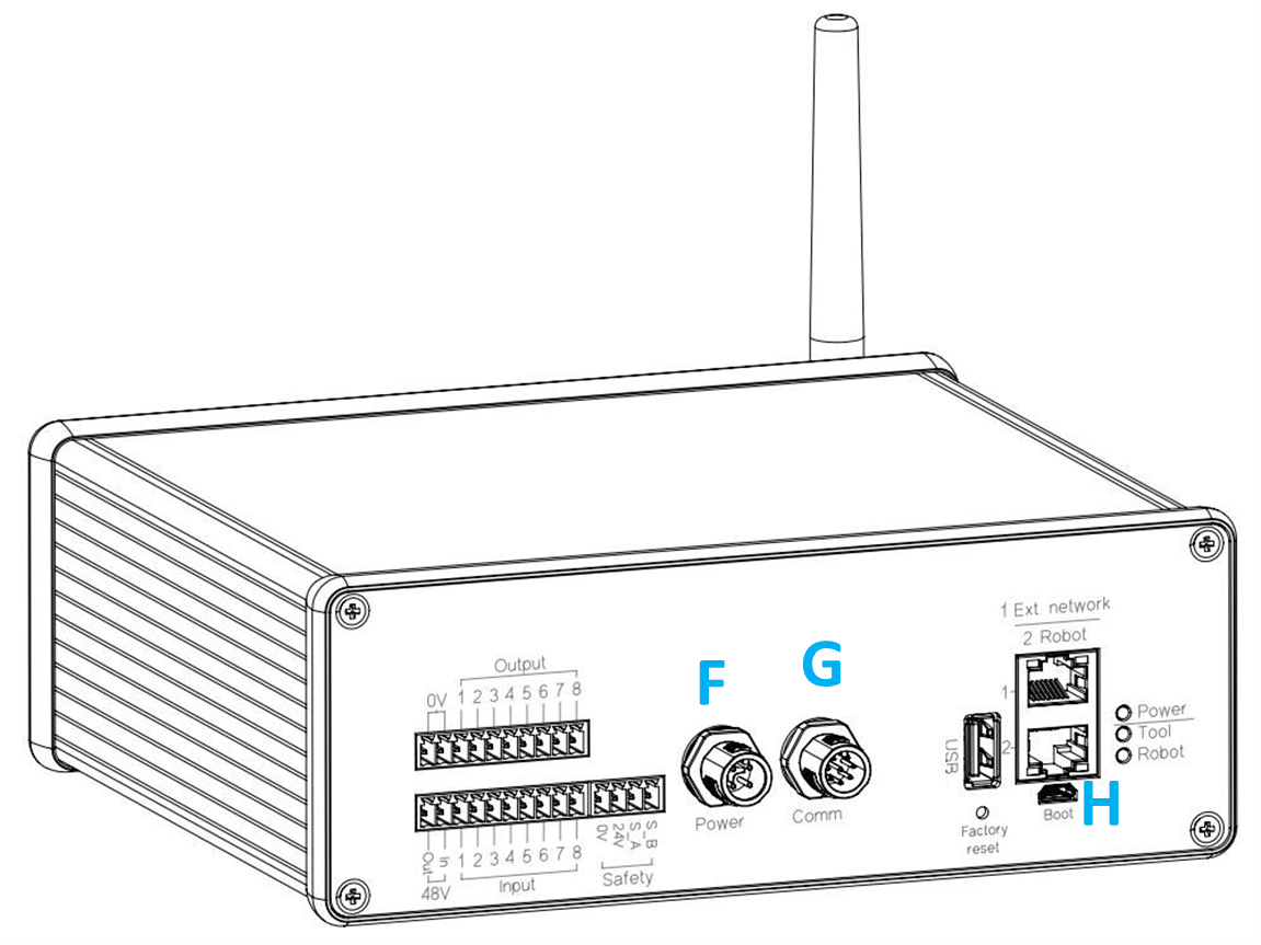
Connect 4-pin power cable to port (F) – Power
Connect 8-pin signal cable to port (G) – Comm
Choose one connection method depending on your system:
Robot integration (Ethernet)
Connect Ethernet cable between robot and SpinBridge port (H) (Robot)
Required when using robot-specific software (e.g. URCap, Kassow Cbun)
I/O integration
Connect digital I/O between robot and SpinBridge
See I/O module for details
Note
When using I/O integration, 24V and 0V from the safety cable must be connected to the robot controller power supply to ensure a common electrical reference.
Note
Only one connection method should be used at a time.
Note
Always use the lower Ethernet port (Port 2 – Robot (H)).
The upper port is for external communication.
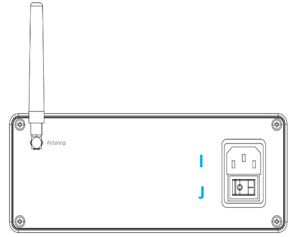
Mount antenna
Connect power cable (I)
Place SpinBridge near robot controller
Connect safety cable (see next step)
Turn on power switch (J)
Tip
Watch SpinBridge installation:

Step 5: Connect Safety Cable
Connect the safety cable to the SpinBridge safety input
Connect the safety outputs to the robot or PLC emergency stop circuit
Connect 24V and 0V to the robot or PLC power supply
Warning
Do NOT operate the system in collaborative applications without the safety cable installed.
Note
Correct safety wiring and functionality must be verified before operation.
See Connecting Safety to Robot or PLC for wiring principles and requirements.
Verification (Quick Check)
After installation:
Power on the system
Trigger the safety sensor (e.g. push the tool upwards)
Confirm that the robot stops
Warning
If the robot does NOT stop:
Do NOT continue operation
Note
Full validation and revalidation requirements are described in Verification and Operation.
Step 6: Connect Ethernet to Robot Controller
Connect an Ethernet cable between the robot controller and the SpinBridge (Robot port)
Configure the robot network settings to match the SpinBridge network
Note
Ethernet connection is required when using robot-integrated software (e.g. URCap or Kassow Cbun).
For network configuration details, refer to the robot manufacturer’s documentation.
Step 7: Mount Magnetic Screw Holder
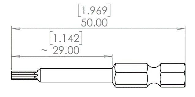
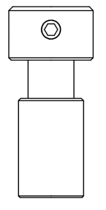
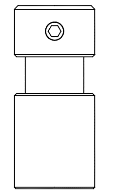
The SD/SDV tools use interchangeable magnetic screw holders.
The system supports 1/4” (6.35 mm) bits with 50 mm length.
Select correct holder size based on screw type:
Magnetic screw holder size |
Small
|
Medium
|
Large
|
||||
|---|---|---|---|---|---|---|---|
Inner diameter ø[mm] |
2.5 |
3 |
4 |
4.5 |
5 |
6 |
|
Outer diameter Ø[mm] |
6 |
8 |
10 |
||||
Typical Screw size |
M1.6-3 |
M3-4 |
M4-6 |
||||
Torx |
|
TX4-9 |
TX10-15 |
TX20 |
TX25-30 |
||
Hex socket |
|
2-3 |
4 |
5-6 |
|||
Phillips |
|
PH 0 |
PH1 |
PH2 |
|||
Pozi drive |
|
PZ1 |
PZ2 |
||||


Step 8: Assemble Bit and Holder
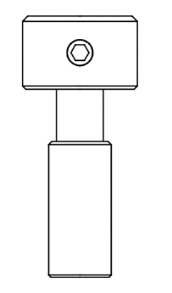
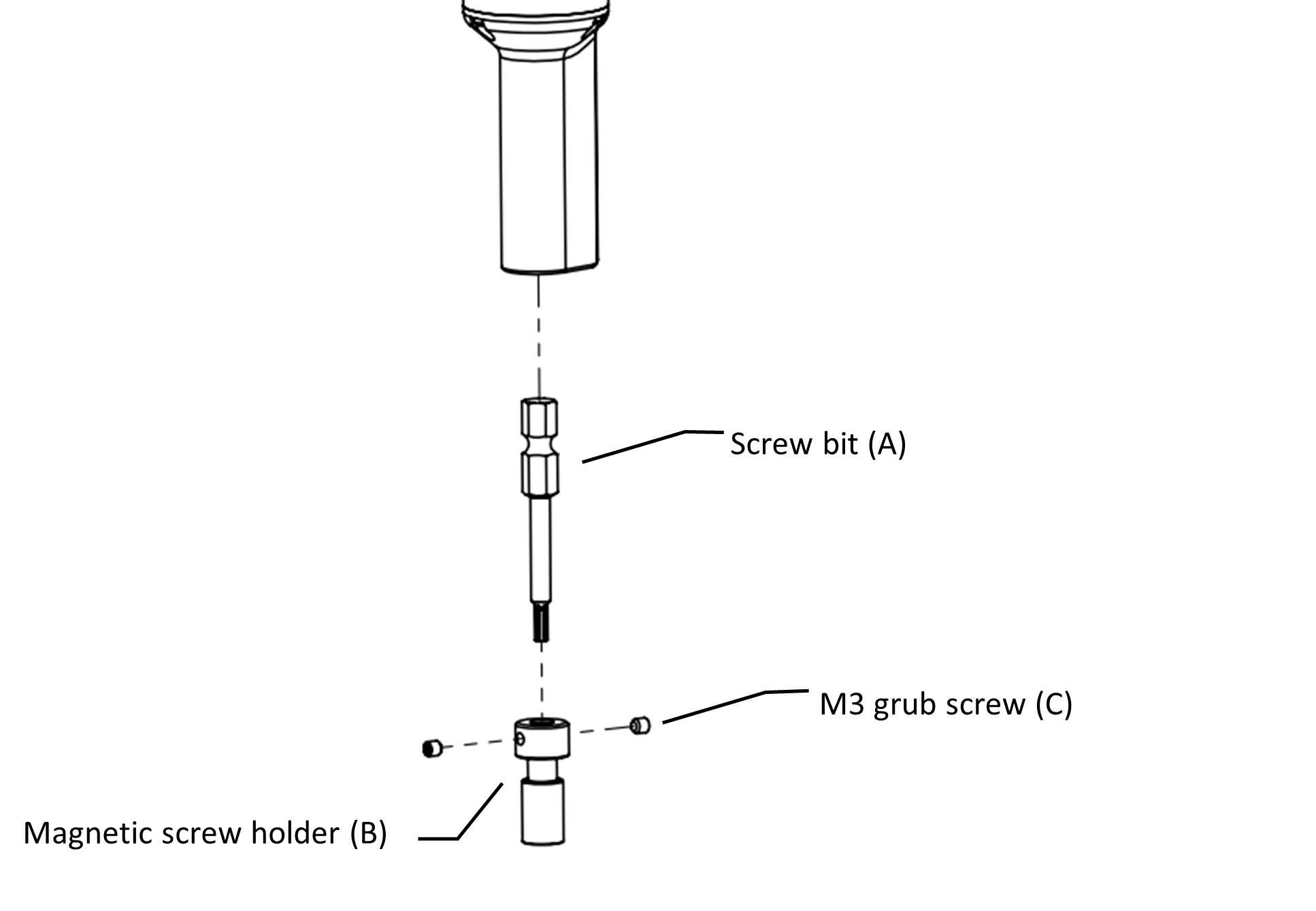
Insert screw bit (A) into magnetic holder (B)
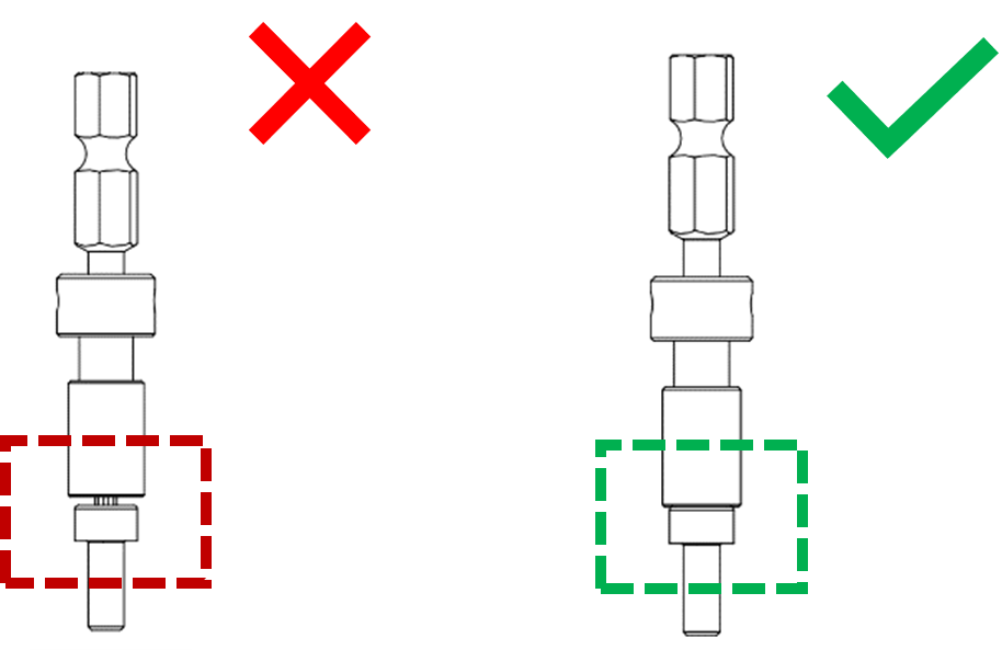
Ensure screw head contacts magnetic ring
Verify screw is centered
Tighten M3 grub screws (C)
Insert assembly into tool
Pull gently to release if needed
Note
Let the screw align naturally with the magnetic holder before tightening.
Tip
Watch bit mounting:

Installation Complete
The hardware installation is now complete.
Proceed to:
Create your first screw program
Program robot motion
Important
A stable process depends on:
Correct screw pickup
Correct step transitions in the screw program
These are the most common sources of errors.