Spin Bridge Pinout
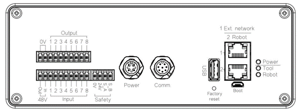
The SpinBridge provides the following electrical interfaces:
4-pin terminal socket for safety (OSSD + 24V/0V supply)
M12 power connector (48V motor supply)
M12 communication connector (tool interface)
USB 2.0 host
2 × Ethernet ports (1: External network, 2: Robot connection)
Factory reset button
USB Micro (service port – do not use)
LED status indicators
Note
The SpinBridge acts as the central interface between:
The SD/SDV-Series tool
The robot or PLC
The safety system
All electrical connections to the tool are routed through the SpinBridge.
Warning
Incorrect wiring or missing connections may result in:
Loss of communication
Failure of safety functions
Unstable system behavior
Always verify all connections before operation.
Safety Terminal (OSSD Interface)
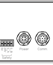
Safety terminal pinout
Pin |
Signal |
|---|---|
1 |
0V (from robot / safety supply) |
2 |
+24V (from robot / safety supply) |
3 |
OSSD A (safety output channel A) |
4 |
OSSD B (safety output channel B) |
Note
The safety interface is powered externally by the robot or PLC.
OSSD signals are dual-channel, pulse-tested safety outputs.
Important
The robot or PLC must monitor both OSSD channels.
A safe stop must be initiated if either channel goes low.
Note
The SpinBridge provides safety-related signals but does not perform the safe stop function.
The safe stop must be implemented by the robot or PLC.
48V Motor Supply Interface
The 48V motor supply is generated and supplied by the SpinBridge.
The internal power supply provides 48V for the screwdriver motor
The supply is internally switched and forwarded to the tool
Note
The 48V circuit can be interrupted via:
Internal control (software)
External safety relay (via I/O connector, 48V motor loop (48V in/out))
Refer to I/O module for details.
Important
Removing the 48V supply ensures that the motor is fully de-energized.
Tool Communication Interface (M12)
The M12 communication connector provides:
RS485 communication
24V supply for tool electronics
Internal routing of safety signals from the tool
Note
Refer to SD/SDV-Series Pinout Interface for detailed pin assignments.
Ethernet Interfaces
The SpinBridge provides two RJ-45 Ethernet ports:
Port 1 – External network (service, configuration, OPC-UA)
Port 2 – Robot connection
Important
Always connect the robot controller to Port 2.
Note
Only one control interface should be active at a time.
USB Interfaces
The SpinBridge includes:
USB Host (for external devices)
USB Micro (service interface - DO NOT USE)
Warning
The USB Micro port is for service use only and must not be used during normal operation.
LED Indicators
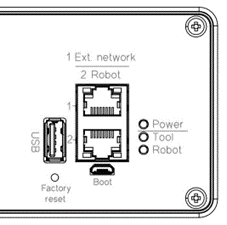
Status LEDs
LED |
Function |
|---|---|
Power |
SpinBridge is powered |
Tool |
Tool is connected and communicating |
Robot |
Robot connection is active |
I/O Module
The I/O module is available on all SpinBridge variants.
It enables control of the SD/SDV-Series without robot-specific software.
Warning
Ensure that both robot and SpinBridge are powered off before connecting the I/O module.
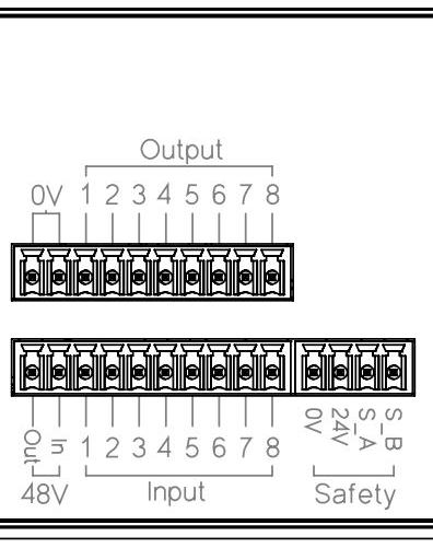
The I/O interface:
Complies with IEC 61131-2
Is galvanically isolated
Is powered externally via the safety connector (24V / 0V from robot)
I/O connector pinout
Pins |
Function |
|---|---|
1–2 |
0V (internal reference for outputs – do not connect to robot 0V) |
3–10 |
Outputs 1–8 (potential-free) |
Pins |
Function |
|---|---|
1 |
48V output |
2 |
48V motor loop (break to disable motor supply) |
3–10 |
Inputs 1–8 (from robot) |
Important
The 48V motor supply loop can be interrupted via the I/O connector.
This allows integration of an external safety relay to ensure complete removal of motor power.
Note
All I/O signals are referenced to the external 24V/0V supply provided by the robot or PLC.
Note
Refer to the Dashboard manual for configuration of I/O functions.