SD/SDV-Series Pinout Interface
This section describes the electrical pinout of the SD/SDV-Series tool connectors.
Two connectors are used:
8-pin M12 connector for communication, control, and safety signals
4-pin M12 connector for motor power (48V)
8-Pin M12 Connector (Communication & Safety)
The 8-pin connector provides power for the tool electronics, RS485 communication, and safety signals.
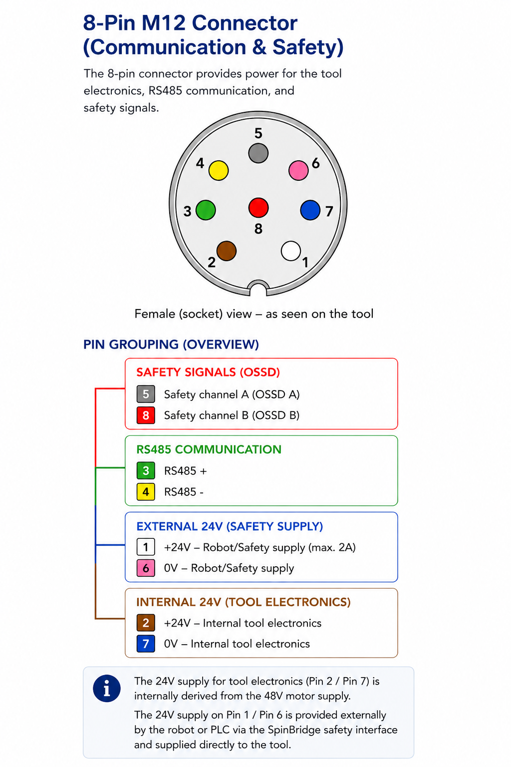
Signal connection pinout
Pin |
Color |
Signal |
|---|---|---|
1 |
White |
+24V (external safety supply, max. 2A) |
2 |
Brown |
+24V (internal tool electronics, derived from 48V) |
3 |
Green |
RS485 + (communication) |
4 |
Yellow |
RS485 - (communication) |
5 |
Gray |
OSSD A (safety channel A) |
6 |
Pink |
0V (external safety supply return) |
7 |
Blue |
0V (internal tool electronics) |
8 |
Red |
OSSD B (safety channel B) |
Note
The 24V supply for tool electronics (Pin 2 / Pin 7) is internally derived from the 48V motor supply.
The 24V supply on Pin 1 / Pin 6 is provided externally by the robot or PLC via the SpinBridge safety interface and supplied directly to the tool.
Important
The communication cable must be shielded and used as specified.
The cable shield contributes to EMC performance and signal stability.
4-Pin M12 Connector (Motor Power)
The 4-pin connector provides power for the screwdriver motor.
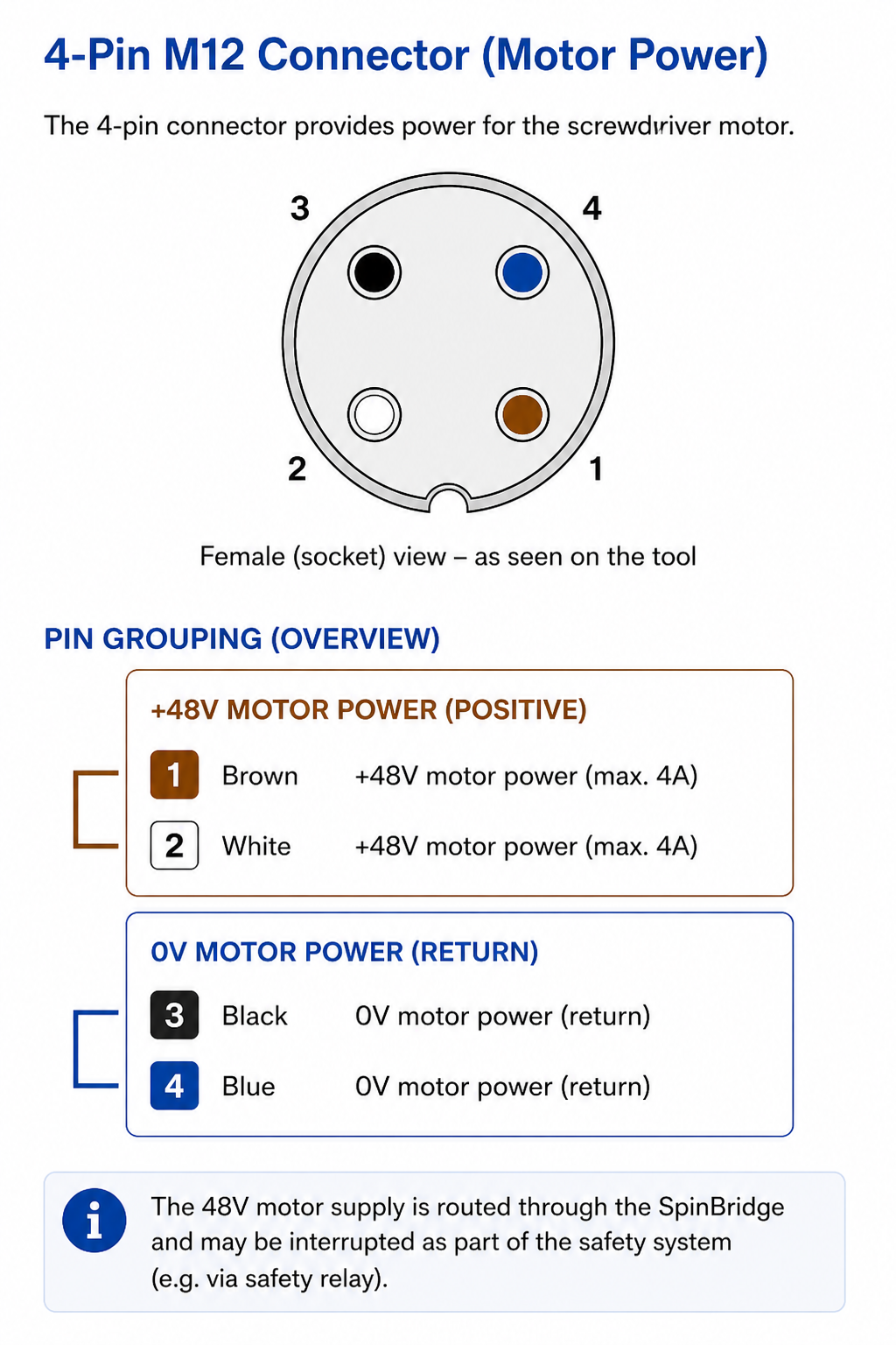
Power connection pinout
Pin |
Color |
Signal |
Description / Function |
|---|---|---|---|
1 |
Brown |
+48V – Motor power (max. 4A) |
Motor supply (positive) |
2 |
White |
+48V – Motor power (max. 4A) |
Motor supply (positive) |
3 |
Black |
0V – Motor power |
Motor supply return |
4 |
Blue |
0V – Motor power |
Motor supply return |
Important
The motor supply must be properly connected and dimensioned according to system requirements.
Note
The 48V supply is routed through the SpinBridge and may be interrupted as part of the safety system (e.g. via safety relay).