Vacuum Integration
The SDV-Series tools support vacuum-based screw pickup.
Vacuum is used to hold a screw at the bit tip during transport from the screw feeder to the fastening position, ensuring reliable and repeatable handling without mechanical clamping.
The tool itself does not generate vacuum. Vacuum must be supplied externally by the integrator.
Note
This section applies to SDV-Series tools only. Standard SD-Series tools do not have a vacuum port.
Vacuum Bits
SDV-Series tools are fitted with vacuum bits — screwdriver bits with an internal vacuum channel that transfers suction from the tool body to the screw head.
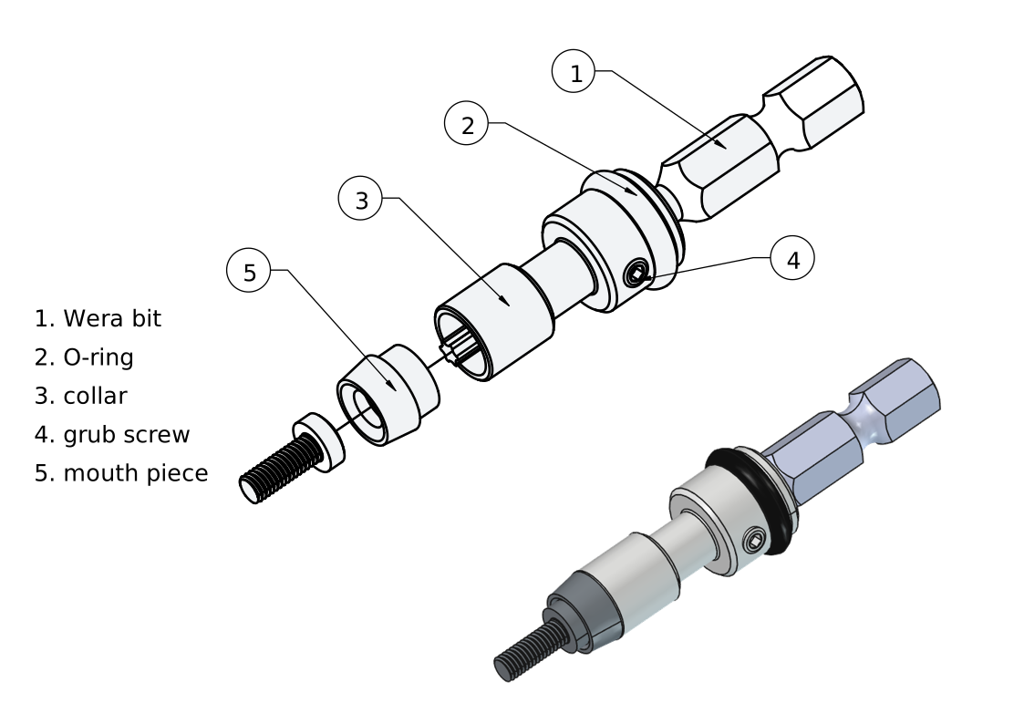
The vacuum channel runs through the collar and opens at the mouthpiece, allowing the screw to be held against the bit face during pickup and transport.
Each vacuum bit assembly consists of three main parts:
Bit — a standard Wera screwdriver bit, matched to the drive recess of the screw
Collar — transfers the suction, sets the bit protrusion and seals against the mouthpiece and safety shield via an O-ring
Mouthpiece — the suction cup that contacts the screw head
The bit, mouthpiece and collar must be selected to match the screw head geometry and drive type. The table below lists all supported combinations.
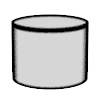
 Hexagon Socket Head Cap Screws — ISO 4762, DIN 912 (withdrawn)
Thread |
Bit |
Wera Ref. |
Mouthpiece |
Collar |
|---|---|---|---|---|
M2.5 |
Hex 2 mm |
840/4 Z |
1001 |
4 |
M3 |
Hex 2.5 mm |
840/4 Z |
1002 |
4 |
M4 |
Hex 3 mm |
840/4 Z |
1003 |
4 |
M5 |
Hex 4 mm |
840/4 Z |
1004 |
5 |
M6 |
Hex 5 mm |
840/4 Z |
1005 |
6 |
 Hexagon Socket Countersunk Head Screws — ISO 10642, DIN 7991
Thread |
Bit |
Wera Ref. |
Mouthpiece |
Collar |
|---|---|---|---|---|
M3 |
Hex 2 mm |
840/4 Z |
1001 |
4 |
M4 |
Hex 2.5 mm |
840/4 Z |
1002 |
4 |
M5 |
Hex 3 mm |
840/4 Z |
1003 |
4 |
M6 |
Hex 4 mm |
840/4 Z |
1004 |
5 |
Note
M2.5 is not yet supported.
 Hexalobular Socket Head Cap Screws — ISO 14579
Thread |
Bit |
Wera Ref. |
Mouthpiece |
Collar |
|---|---|---|---|---|
M2.5 |
TX8 |
867/4 Z |
1101 |
3 |
M3 |
TX10 |
867/4 Z |
1102 |
4 |
M4 |
TX20 |
867/4 Z |
1103 |
4.5 |
M5 |
TX25 |
867/4 Z |
1104 |
6 |
M6 |
TX30 |
867/4 Z |
1105 |
6 |
Hexalobular Socket Cheese Head Screws — ISO 14580
Thread |
Bit |
Wera Ref. |
Mouthpiece |
Collar |
|---|---|---|---|---|
M2.5 |
TX8 |
867/4 Z |
1101 |
3 |
M3 |
TX10 |
867/4 Z |
1102 |
4 |
M4 |
TX20 |
867/4 Z |
1103 |
4.5 |
M5 |
TX25 |
867/4 Z |
1104 |
6 |
M6 |
TX30 |
867/4 Z |
1105 |
6 |
Hexalobular Socket Countersunk Head Screws — ISO 14581, ISO 14582
Thread |
Bit |
Wera Ref. |
Mouthpiece |
Collar |
|---|---|---|---|---|
M2.5 |
TX8 |
867/4 Z |
1101 |
3 |
M3 |
TX10 |
867/4 Z |
1102 |
4 |
M4 |
TX20 |
867/4 Z |
1103 |
4.5 |
M5 |
TX25 |
867/4 Z |
1104 |
6 |
M6 |
TX30 |
867/4 Z |
1105 |
6 |
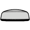 Hexalobular Socket Pan Head Screws — ISO 14583
Thread |
Bit |
Wera Ref. |
Mouthpiece |
Collar |
|---|---|---|---|---|
M2.5 |
TX8 |
867/4 Z |
1201 |
3 |
M3 |
TX10 |
867/4 Z |
1202 |
4 |
(M3.5) |
TX15 |
867/4 Z |
1203 |
4 |
M4 |
TX20 |
867/4 Z |
1204 |
4.5 |
M5 |
TX25 |
867/4 Z |
1205 |
6 |
M6 |
TX30 |
867/4 Z |
1206 |
6 |
Hexalobular Socket Pan Head Tapping Screws — ISO 14585
Thread |
Bit |
Wera Ref. |
Mouthpiece |
Collar |
|---|---|---|---|---|
ST2.9 |
TX10 |
867/4 Z |
1202 |
4 |
ST3.5 |
TX15 |
867/4 Z |
1203 |
4 |
ST4.2 |
TX20 |
867/4 Z |
1204 |
4.5 |
ST4.8 |
TX25 |
867/4 Z |
1205 |
6 |
ST6.3 |
TX30 |
867/4 Z |
1206 |
6 |
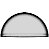 Hexalobular Socket Button Head Screws — ISO 7380-3, DIN 34805-1
Thread |
Bit |
Wera Ref. |
Mouthpiece |
Collar |
|---|---|---|---|---|
M3 |
TX10 |
867/4 Z |
1301 |
4 |
M4 |
TX20 |
867/4 Z |
1302 |
4.5 |
M5 |
TX25 |
867/4 Z |
1303 |
6 |
M6 |
TX30 |
867/4 Z |
1304 |
6 |
 Countersunk Head Screws, Phillips — ISO 7046, ISO 7050, DIN 965 A (withdrawn)
Thread |
Bit |
Wera Ref. |
Mouthpiece |
Collar |
|---|---|---|---|---|
M2.5 |
PH1 |
851/4 J |
1401 |
4.5 |
M3 |
PH1 |
851/4 J |
1402 |
4.5 |
M4 |
PH2 |
851/4 R |
1403 |
3 |
M5 |
PH2 |
851/4 R |
1403 |
3 |
Pan Head Screws, Phillips — ISO 7045, DIN 7985 A (withdrawn)
Thread |
Bit |
Wera Ref. |
Mouthpiece |
Collar |
|---|---|---|---|---|
M2.5 |
PH1 |
851/4 J |
1501 |
4.5 |
M3 |
PH1 |
851/4 J |
1502 |
4.5 |
M4 |
PH2 |
851/4 R |
1503 |
3 |
M5 |
PH2 |
851/4 R |
1504 |
3 |
Note
PH2 combinations (M4, M5) require reduced-tip bits (Wera 851/4 R).
System Responsibility
Vacuum must be supplied externally by the integrator using:
A vacuum pump
A vacuum generator (e.g. venturi system)
The vacuum system must be connected to the tool via the 6 mm push-in connector on the SDV tool body.
Vacuum Requirements
The vacuum system must be capable of:
Maintaining a continuous vacuum during operation
Compensating for leakage in the system
Achieving a minimum vacuum level of approximately 60% vacuum (approximately -600 mbar) at the tool port
Important
The vacuum system must not rely on a sealed system.
The SDV-Series is not fully airtight, and continuous vacuum generation is required during screw pickup and transport.
Minimum Performance
A minimum vacuum level of approximately 60% vacuum is required for reliable screw pickup.
Note
The required vacuum level may vary depending on:
Screw size and weight
Screw head geometry
Screw material and surface finish
Application conditions (speed, acceleration, orientation)
Always validate vacuum performance in the final application.
Pneumatic Connection
The vacuum port on the SDV-Series tool accepts 6 mm OD push-in tubing.
Connect the vacuum supply using:
6 mm OD polyurethane (PU) or polyamide (PA) tubing
A compatible 6 mm push-in fitting
Important
Ensure tubing is fully inserted into the fitting until it seats. Incomplete insertion is a common cause of leakage and reduced vacuum performance.
To disconnect tubing, depress the collet ring on the fitting before pulling the tube free.
System Behavior
If insufficient vacuum is provided:
Screws may not be picked up
Screws may be dropped during transport
Process reliability and cycle time are reduced
If vacuum is lost mid-cycle:
The screw may fall before reaching the fastening position
The robot program should detect the fault and stop the cycle
Application Notes
Note
Vacuum performance depends on the complete system, including:
Tubing length and diameter
Fittings and connectors
Leakage points
Vacuum generator performance
Always validate vacuum performance in the final application.
Integration Responsibility
Important
The integrator is responsible for:
Providing and dimensioning the vacuum system
Ensuring stable vacuum levels during operation
Routing and securing tubing to avoid interference with robot motion
Implementing vacuum control via the robot controller or PLC
Monitoring vacuum performance if process reliability requires it
Vacuum Monitoring
A vacuum sensor installed in the supply line allows the robot controller to verify that a screw has been successfully picked up and is held securely during transport.
Without vacuum monitoring, a dropped or missing screw may not be detected until a failed fastening attempt — increasing cycle time and the risk of producing a non-conforming assembly.
When to use vacuum monitoring
Vacuum monitoring is recommended when:
Process reliability requirements are high
Screw drop events are difficult to detect by other means
The application uses small or lightweight screws that are sensitive to vacuum variation
Sensor placement
Mount the vacuum sensor in the vacuum supply line, as close to the tool as practically possible.
A sensor positioned far from the tool may respond slowly to leakage at the tool tip. Minimising the tubing volume between the sensor and the tool improves response time.
Simple threshold monitoring
The most basic approach is a single switching threshold:
Configure a switching point at a level below the expected operating vacuum (e.g. threshold at -500 mbar for a system running at -650 mbar)
Connect the switching output to a robot digital input
Read the output after a fixed wait time following vacuum activation
If the input is not set within the expected time, no screw is present or vacuum has been lost.
Note
Fixed-threshold monitoring does not distinguish between a screw that is present but held weakly and a screw that is missing entirely. For high-reliability applications, consider using Auto Difference Monitoring instead.
Note
False negatives can occur when the bit sits tightly inside the screw socket. In this situation the screw is correctly held, but vacuum may read low for unrelated reasons, causing the monitoring to report a fault even though no screw has been dropped.
If this is a concern for your application, an optical sensor can be added to provide independent confirmation of screw presence.
Recommended Sensor: Festo SPAN-V1R-Q4-PNLK-PNVBA-L1
Spin Robotics recommends the Festo SPAN-V1R-Q4-PNLK-PNVBA-L1 vacuum pressure sensor for monitoring vacuum in SDV-Series installations.
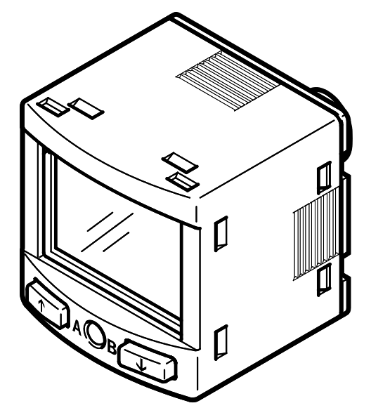
This sensor covers the full vacuum range (0 to -1 bar) and supports Auto Difference Monitoring — a built-in function that adapts to the operating vacuum level and detects deviations caused by leakage or a missing screw.
Key specifications
Parameter |
Value |
|---|---|
Measuring range |
0 … -1000 mbar |
Supply voltage |
15 … 30 V DC (24 V rated) |
Switching outputs |
2× PNP (or NPN) |
Switching functions |
Threshold, Window, Auto Difference Monitoring |
Switch-on/off time |
Typical 2 ms |
Protection class |
IP40 |
Connector |
4-pin, L1 |
Wiring
Pin |
Wire color |
Signal |
Function |
|---|---|---|---|
1 |
Brown (BN) |
+24 V |
Supply voltage |
2 |
Black (BK) |
OutA |
Switching output → connect to robot digital input |
3 |
White (WH) |
OutB |
Analogue / second output — not used |
4 |
Blue (BU) |
0 V |
Supply reference |
Connect OutA (pin 2, black) to a robot digital input. Connect +24 V (pin 1, brown) and 0 V (pin 4, blue) to the robot or external 24 V supply.
Important
The 0 V reference of the sensor supply must be shared with the robot or PLC digital input reference.
A missing common reference will cause unreliable or absent switching signals.
Changing the Display Unit
The SPAN sensor ships with bar as the default display unit. Change it to mbar before commissioning so that the values shown on the display and used during parameter entry match the units in this manual.
Ensure the sensor is powered and in RUN mode (pressure value displayed).
Press [Edit] briefly → Edit appears, OutA flashes.
Use [A] or [B] to navigate to Spec → Spec flashes.
Press [Edit] briefly → Filt flashes (first item in the Spec menu).
Press [Edit] briefly to accept the current Filt value and advance → Unit flashes.
Use [A] or [B] to select mbar.
Press [Edit] to confirm.
Press and hold [Edit] for 3 seconds to return to RUN mode.
Note
The display now shows vacuum in mbar (e.g. -650 for -650 mbar). All switching-point parameters (SP.Lo, SP.Hi, d.SP) are also entered and displayed in mbar after the unit change.
Auto Difference Monitoring
Auto Difference Monitoring is a built-in function of the Festo SPAN sensor that automatically learns the stable vacuum level after screw pickup and switches the output if the vacuum subsequently drops — for example because the screw has fallen off the bit during transport.
Unlike a fixed threshold, Auto Difference Monitoring adapts to the actual operating vacuum level of the system. This makes it robust against variation in vacuum source pressure, tubing length, and screw geometry without requiring manual recalibration.
How it works
When vacuum is activated and the pressure enters the valid range (between SP.Lo and SP.Hi), the sensor observes the signal for a configurable averaging period (t.obS).
At the end of the observation period, the average pressure is stored as the reference value (PRef). The switching output activates to indicate that vacuum is established.
During transport, the sensor monitors the vacuum level continuously. If the pressure deviates from PRef by more than the differential threshold (d.SP), the output switches off — indicating leakage or a dropped screw.
Configuration parameters
Parameter |
Description |
Recommended value |
|---|---|---|
SP.Lo |
Low absolute vacuum bound (less vacuum) |
-550 mbar |
SP.Hi |
High absolute vacuum bound (more vacuum) |
-750 mbar |
t.obS |
Observation time for averaging (ms) |
200 – 500 ms |
d.SP |
Differential threshold: deviation from PRef that triggers a fault |
50 – 100 mbar |
LOGC |
Output logic |
NO (normally open) |
Note
The recommended values above are starting points. Validate and adjust based on the actual vacuum level in your application.
SP.Lo is the lower absolute vacuum value (less negative, e.g. -550 mbar) and SP.Hi is the higher absolute vacuum value (more negative, e.g. -750 mbar). For a system running at -650 mbar, set SP.Lo below and SP.Hi above that operating point.
Increase d.SP if the system produces false faults during normal operation. Decrease d.SP for higher sensitivity to leakage.
Configuration procedure
To configure Auto Difference Monitoring on the SPAN sensor:
Ensure the sensor is powered and in RUN mode (pressure value displayed).
Press [Edit] briefly → Edit appears, OutA flashes.
Press [Edit] briefly → Fctn flashes.
Use [A] or [B] to select
d_|‾|_(Auto difference monitor function).Press [Edit] to confirm → first parameter (SP.Lo) is displayed.
Set SP.Lo using [A] / [B], then press [Edit] to confirm.
Set SP.Hi using [A] / [B], then press [Edit] to confirm.
Set t.obS (observation time in ms) and confirm with [Edit].
Set d.SP (differential threshold) and confirm with [Edit].
Set LOGC to NO (output active when vacuum stable) and confirm.
Press and hold [Edit] for 3 seconds → sensor returns to RUN mode.
Note
For full details on commissioning, TEACH mode, and IO-Link integration, refer to the Festo SPAN operating instructions (document 8225842).