SD35/70 pinout interface
The table below illustrates the cable pinout at the SD35/70 tool input.
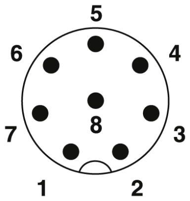
Signal connection pinout |
||
|---|---|---|
Pin |
Color |
Signal |
1 |
White |
+24V – Robot/Safety supply (max. 2A) |
2 |
Brown |
+24V – Main power |
3 |
Green |
RS485 + |
4 |
Yellow |
RS485 - |
5 |
Gray |
SAFETY A |
6 |
Pink |
0V – Robot/Safety supply |
7 |
Blue |
GND – Main Power supply |
8 |
Red |
SAFETY B - OSSD |
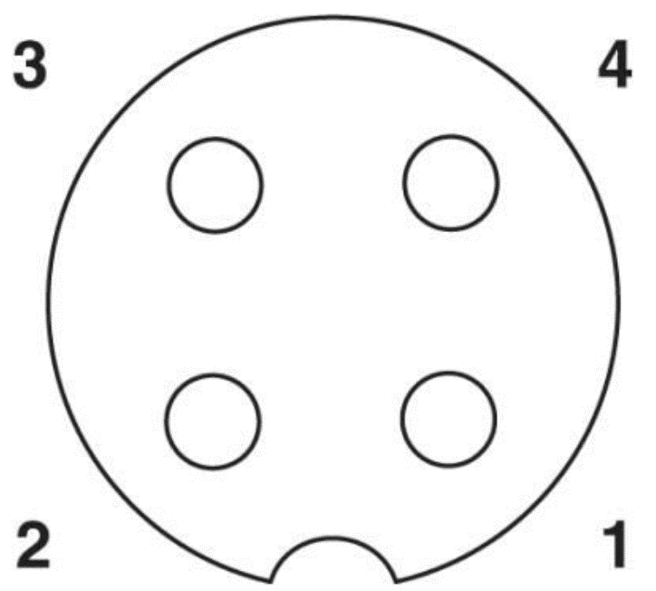
Power connection pinout |
||
|---|---|---|
Pin |
Color |
Signal |
1 |
Brown |
+48V - Motor power (max. 4A) |
2 |
White |
+48V - Motor power (max. 4A) |
3 |
Black |
GND - Motor power |
4 |
Blue |
GND - Motor Power |