Spin Bridge pinout
The SpinBridge consists of the following electrical interfaces:
1 x 4-pin terminal socket with OSSD safety signal output & 24V/0V to supply the safety system
1 x M12 Power Connector to supply the SD35/70 drive motor with 48V
1 x M12 Communication connector to communicate with the SD35/70 tool
1 x USB 2.0 Host
2 x ethernet ports (1: Ext. Network, 2: Robot connection)
1 x Factory reset button
1 x USB Micro Slave (only used for factory software booting. DO NOT USE THIS)
3 x LED indicators
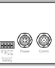
Safety terminal socket pinout |
|
|---|---|
Pin |
Signal |
1 |
GND (0V from robot) |
2 |
24V - Power to safety sensor (24V) from robot) |
3 |
OSSD1 - Safety signal A (S_A) |
4 |
OSSD1 - Safety signal B (S_B) |
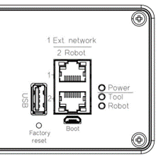
Spin Bridge LED indicators |
|
|---|---|
Pin |
Function |
Power |
The Spin Bridge is powered |
Tool |
The Spin Bridge is connected to the tool |
Robot |
The Spin Bridge is connected to the robot |