Spin Bridge pinout
The SpinBridge consists of the following electrical interfaces:
1 x 4-pin terminal socket with OSSD safety signal output & 24V/0V to supply the safety system
1 x M12 Power Connector to supply the SD35/70 drive motor with 48V
1 x M12 Communication connector to communicate with the SD35/70 tool
1 x USB 2.0 Host
2 x ethernet ports (1: Ext. Network, 2: Robot connection)
1 x Factory reset button
1 x USB Micro Slave (only used for factory software booting. DO NOT USE THIS)
3 x LED indicators
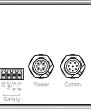
Safety terminal socket pinout |
|
|---|---|
Pin |
Signal |
1 |
GND (0V from robot) |
2 |
24V - Power to safety sensor (24V) from robot) |
3 |
OSSD1 - Safety signal A (S_A) |
4 |
OSSD1 - Safety signal B (S_B) |
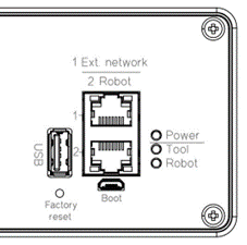
Spin Bridge LED indicators |
|
|---|---|
Pin |
Function |
Power |
The Spin Bridge is powered |
Tool |
The Spin Bridge is connected to the tool |
Robot |
The Spin Bridge is connected to the robot |
I/O module
This module is available on the I/O variant of the Spin Bridge. With this module, you can connect a generic robot to the SpinBridge and control the screwdriving system without any additional robot software.
Warning
Before connecting the I/O module to a robot, ensure that the robot and the Spin Bridge are powered off to prevent any electrical damage.
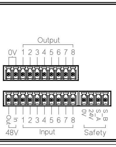
The module conforms to IEC 61131-2 and is externally powered via the 0V and 24V inputs in the Safety section. When the safety circuit is connected to the robot, the module will be powered by the robot.
Spin Bridge I/O connectors |
|
|---|---|
Pin |
Output connector |
1-2 |
0V output - do not connect to robot |
3-10 |
Outputs 1-8 to robot - potential free |
Pin |
Input connector |
1 |
48V output |
2 |
48V motor input - break to shut off motor |
3-10 |
Inputs 1-8 from robot |
See the Dashboard manual for information on how to control the screwdriver with the I/O module.