How to install
Unpack the box and make yourself familiar with the components inside it.
Quick Changer Mounting
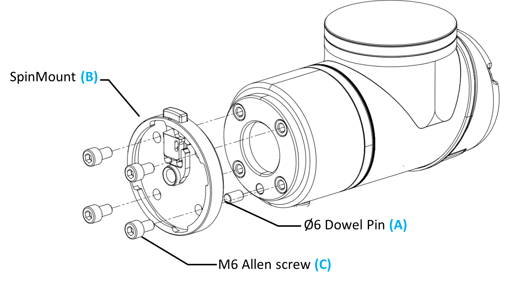
Place the supplied Dowel pin (A) inside of the UR flange so that you can easily find the right position for the SpinMount. Note: It is important to mount is correctly to use the predefined Tool Center Point (TCP) in the URCap.
Mount the SpinMount (B) (robot side) on the robot using the four supplied M6 Allen screws (C) and the Allen key, as shown on the picture below. Use 8 Nm tightening torque.
Mount the tool
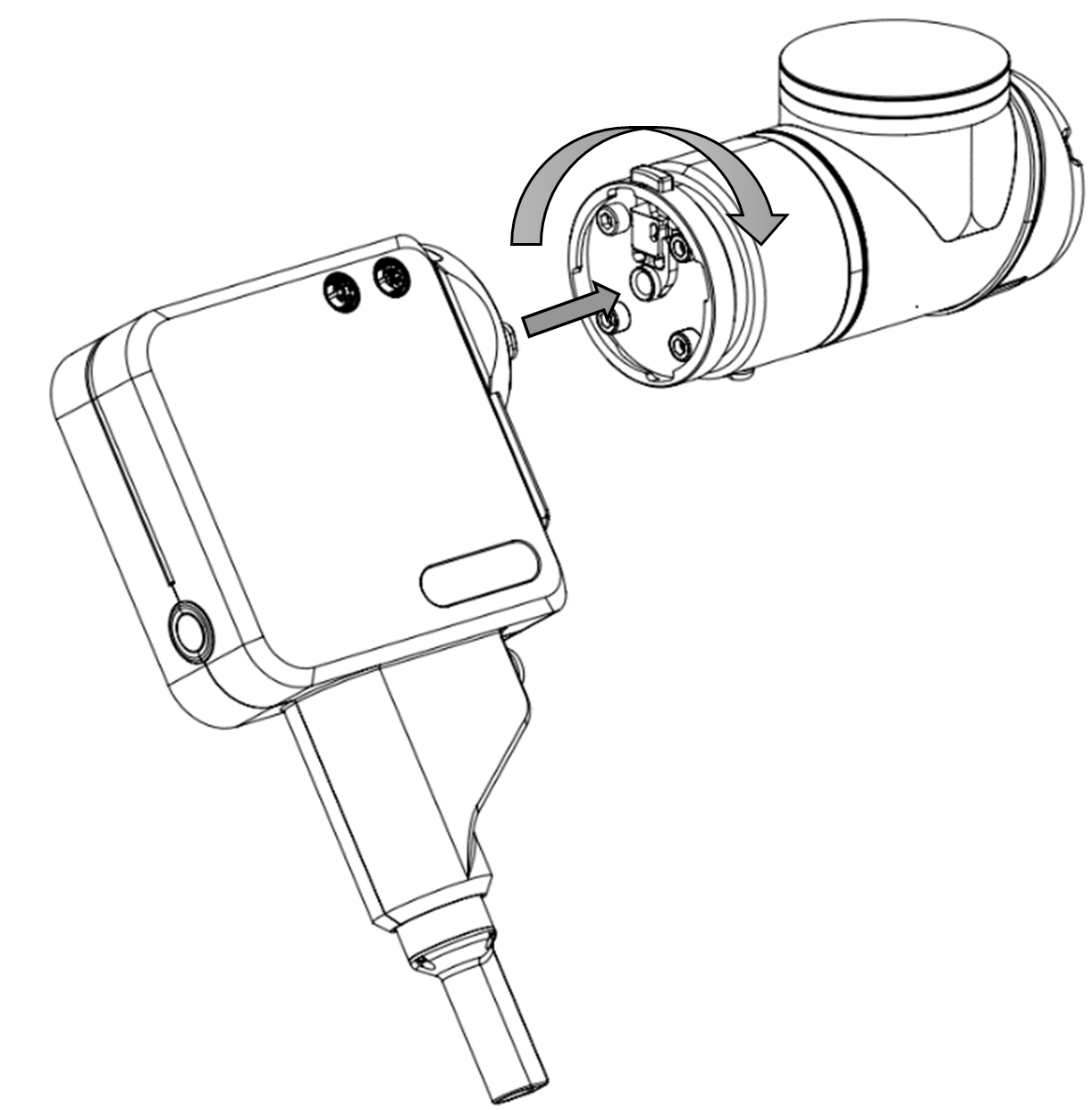
Push and rotate the SD35/70 in clockwise direction until you hear a ‘click’.
Connect the cables to the tool
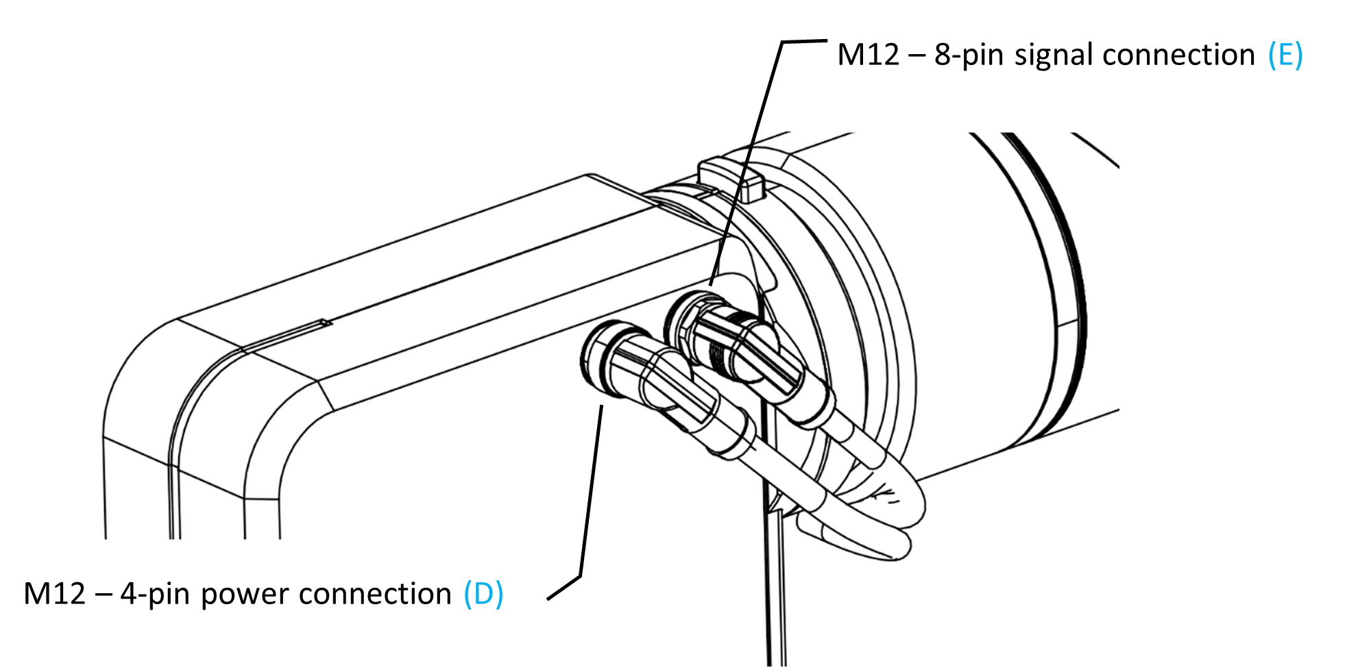
Connect the M12 – 4-pin power cable (D) to the front port as shown on the picture.
Connect the M12 – 8-pin signal cable (E) to the back port as shown on the picture.
Fasten cables on the robot by using supplied Velcro straps. Add extra bending radius to not damage the cables during robot motion. Do not fasten the cables tens to the robot but add extra cable length near all robot joints.
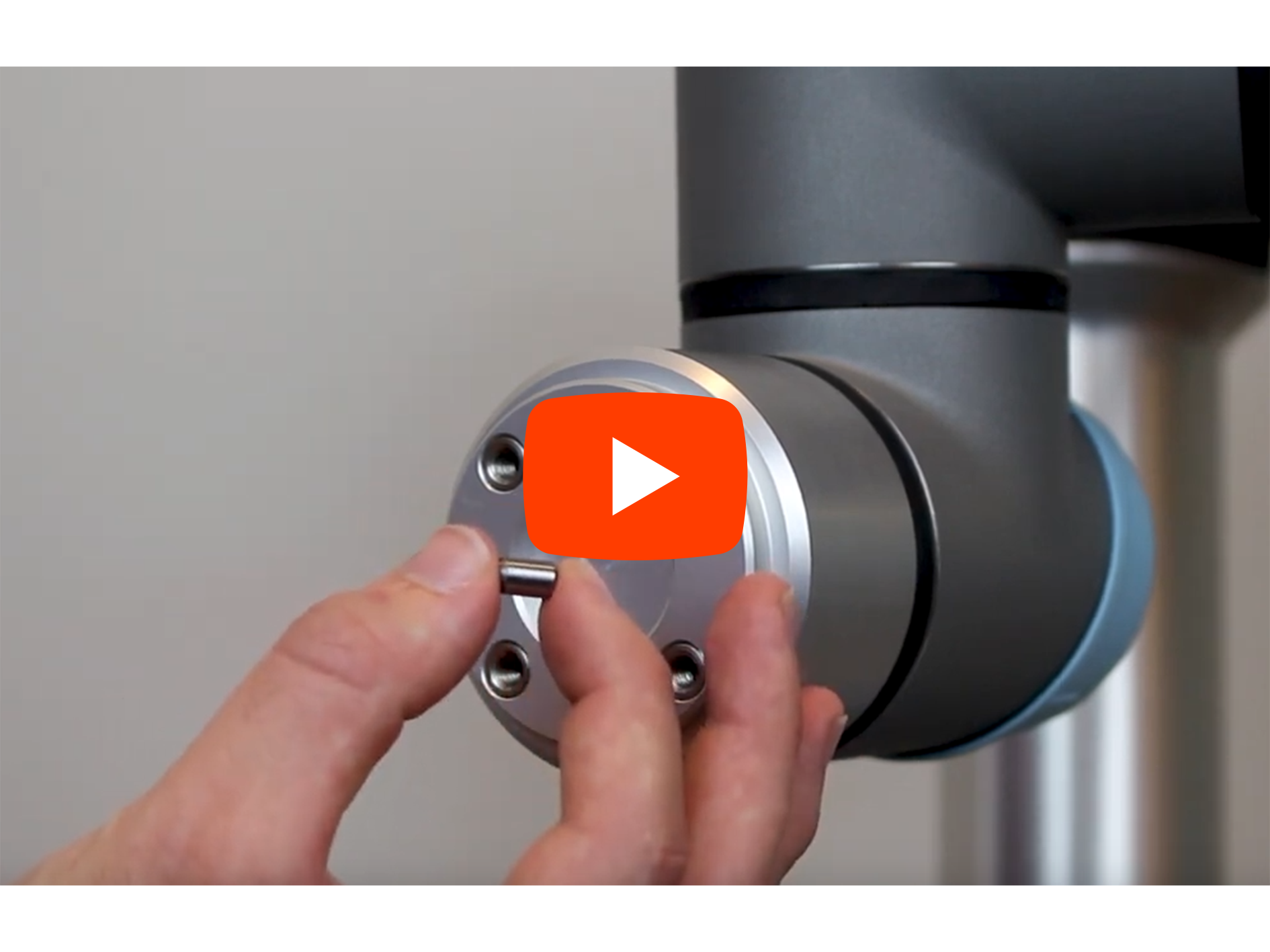
At the video below the installation of the SpinMount and the tool demonstrated.
Connect SpinBridge
Connect the cables from SD35/70 to the SpinBridge:
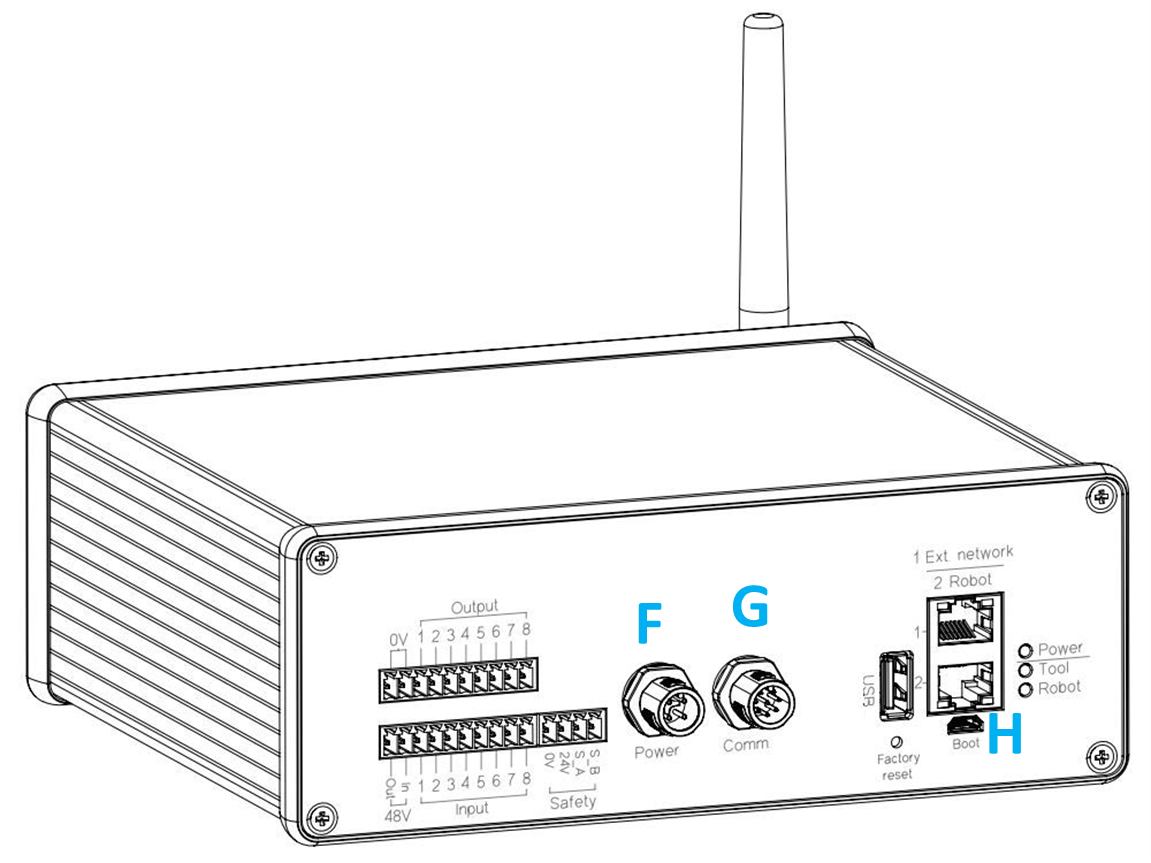
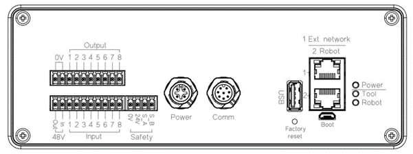
Connect the 4-pin power cable to the left port (F) - Power.
Connect the 8-pin signal cable to the right port (G) - Comm.
Connect the ethernet cable to the lower ethernet port (H) at the SpinBridge
Note
Remember to insert the ethernet connected to the robot controller in the lower ethernet plug (Port 2 Robot (H)) in the SpinBridge. The upper ethernet plug is for external communication.
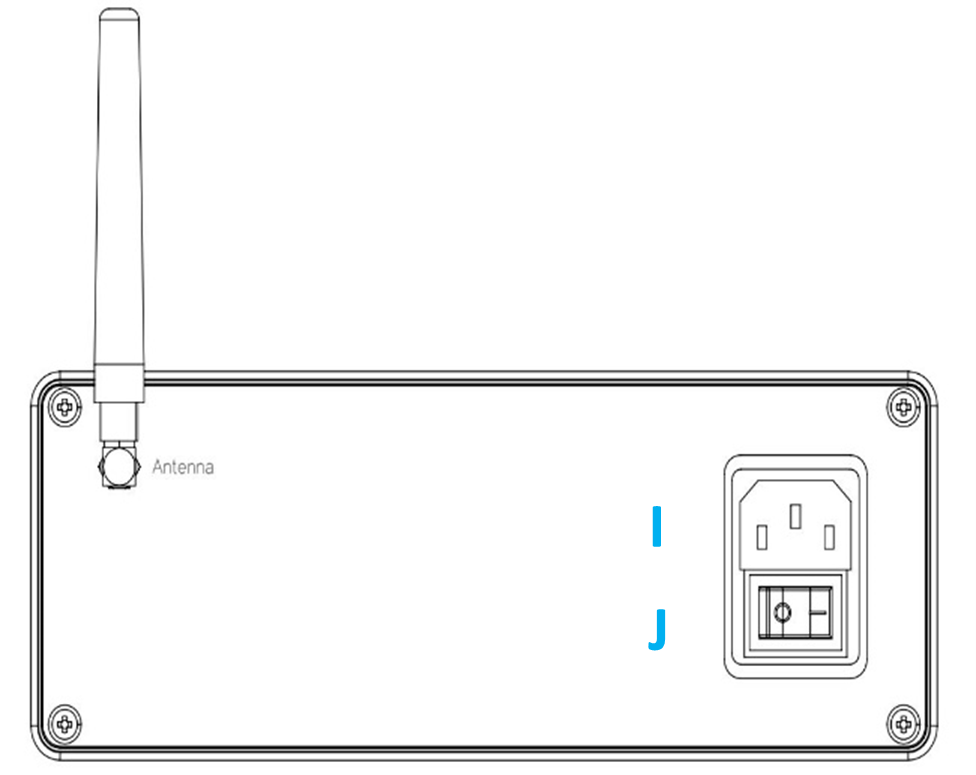
Mount the Antenna (I) at the back of the SpinBridge.
Plug in the main power cable (J)
Place the Spin Bridge next to the robot controller to keep it secure
When all cables incl. the safety cable LINK!! (Section 4.2.5), turn on the power switch (K)
At the video below the installation of the Spin Bridge are demonstrated.

Connect Safety Cable to the Robot Controller
Warning
Do not install the SD35/70 in a collaborative application without installing the safety cable between the robot controller and the SpinBridge.
To ensure that the robot stops when the internal safety system in the SpinBridge safety output much be connected to the robot controller emergency stop terminal.
Mounting Universal Robots safety cable
Connect the Safety cables black plug to the Safety input connector (K) at the SpinBridge (4-pin Safety input).
Connect the yellow plug of the safety cable to the Universal Robots emergency input in the e-series controller (L)
Connect the gray plug of the safety cable to the Universal Robots 4 pin power plug (M)
Mounting Kassow Robots safety kit
The SpinBridge and a Kassow Robot must be interconnected with a Kassow Safety Kit supplied by Spin Robotics. The Safety Kit includes a Safety Relay, that translates OSSD safety signals from the tool safety sensor to the Kassow Robot.

The Kassow Safety Kit comes preassembled with a safety relay but must be connected to the robot controller and the SpinBridge.
Connect the safety cables black plug to the safety input connector (K) at the SpinBridge 4-pin Safety input.
Connect the gray 4-pin plug of the safety cable to the 4-pin Kassow Robots Emergency Stop input socket in the controller box.
Connect the gray 2-pin plug of the safety cable to the Kassow Robots 2-pin power socket in the controller box.
Connect Ethernet Cable to the Robot Controller
Connect the ethernet cable to the ethernet port in the robot controller (N).
Mounting Magnetic Screw Holder
This section explains the correct mounting of a ‘magnetic screw holder’ and bit. The SD35/70 are supplied with 6 Magnetic Screw Holders in different sizes. Each of the 6 Magnetics Screw Holders fits different screw bit head types and two different bit shaft diameters.
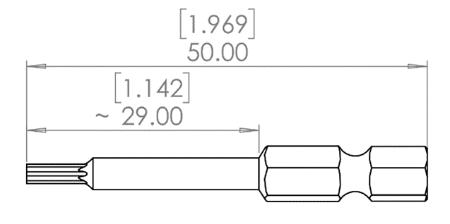
The tool and the magnetic screw holders are compatible with ¼”/6.35mm bits with a total length of 50mm. Bits can be purchased by contacting the vendor which the tool has been purchased from or from local wholesales.
Magnetic screw holder size |
Small
|
Medium
|
Large
|
||||
|---|---|---|---|---|---|---|---|
Inner diameter ø[mm] |
2.5 |
3 |
4 |
4.5 |
5 |
6 |
|
Outer diameter Ø[mm] |
6 |
8 |
10 |
||||
Typical Screw size |
M1.6-3 |
M3-4 |
M4-6 |
||||
Torx |
|
TX4-9 |
TX10-15 |
TX20 |
TX25-30 |
||
Hex socket |
|
2-3 |
4 |
5-6 |
|||
Phillips |
|
PH 0 |
PH1 |
PH2 |
|||
Pozi drive |
|
PZ1 |
PZ2 |
||||
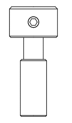
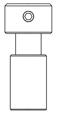
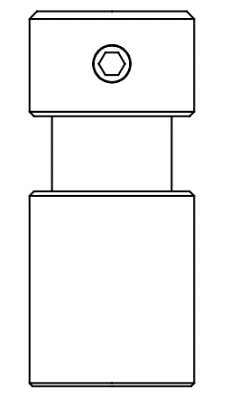


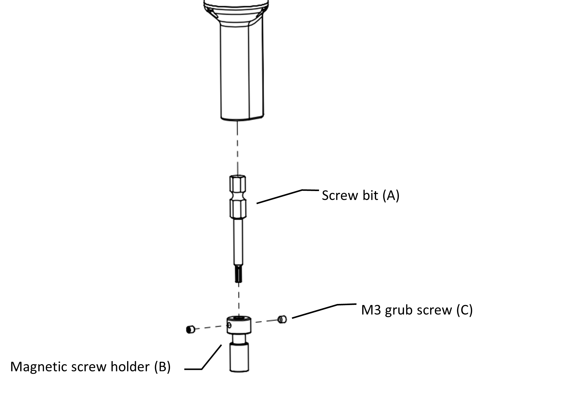
Insert your screw bit (A) into the supplied magnetic screw holder (B).
Before fastening the bit in the magnetic screw holder, check that the screw head surface meets the magnetic ring on the screw holder (see picture below).
Check that the screw is centered.
Make sure to tighten the two M3 grub screws (C) on the sides. It is recommended to apply a medium strength Loctite to the M3 grub screws for secure assembly.
The bit including the magnetic screw holder can now be inserted into the end of the SD35/70 where it is held firm by a locking mechanism.
The bit can be released in the SD35/70 tool with a gentle pull.
Note
The optimal position of the magnetic screw holder (B) is easily ensured by letting the screw and the magnetic screw holder (B) attract each other as far as possible while allowing the screw bit (A) to rest at the bottom of the screw head notch before tightening the grub screws (C).
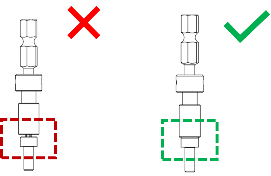
At the video below the installation of the bitmagnets are demonstrated.