Maintenance and Repair
All maintenance and repairs must be performed in compliance with this manual, including safety instructions. Only authorized system integrators, or Spin Robotics, shall perform repairs. Unauthorized repairs can lead to warranty void.
Warning
Only use original spare parts.
Warning
Always turn off the robot and screwdriver power supply before doing maintenance operations on the screwdriver.
The screwdriver requires only external maintenance, no maintenance is required on the inside. If in need of maintenance on the inside of the tool, please contact the vendor where the tool has been purchased. SD35/70 is not waterproof, proper cleaning should be done on the screwdriver with a dry cloth, with no chemicals, on monthly basis.
Spin Robotics recommends the user does not attempt repair, adjust, or make other interventions in the mechanical or electrical systems of the tool without first consulting a SPIN Robotics certified service engineer. Any unauthorized intervention voids the warranty. Service-related operations and troubleshooting should only be performed by qualified personnel. Before performing service-related operations, stop the robot program and disconnect the main power to the tool on the robot. In the event of a defect, Spin Robotics recommends ordering new parts from a Spin Robotics distributor where the tool was originally purchased. Alternatively, parts can be ordered from the nearest distributor, details of which can be obtained from Spin Robotics’ official website at www.spin-robotics.com .
Inspection Plan
The table below is a checklist of the type of inspections recommended by Spin Robotics. Perform inspections regularly as advised on the table. Any referenced parts found to be in an unacceptable state must be rectified or replaced.
Inspection Plan |
Timeframe |
|||
|---|---|---|---|---|
Weekly |
Monthly |
Biannually |
||
1 |
Clean bit head |
X |
||
2 |
Clean screwdriver tool |
X |
||
3 |
Check bit head |
X |
||
4 |
Check power and communication cable connection |
X |
||
5 |
Check bit locking mechanism |
X |
||
6 |
Check the safety system* |
X |
||
7 |
Check tool sledge mechanism* clearance |
X |
||
8 |
Check freedrive |
X |
||
9 |
Check front button |
X |
||
10 |
Check SpinMount quick coupling* |
X |
||
11 |
Calibrate tool |
X |
||
12 |
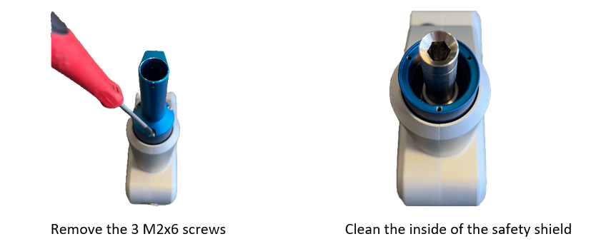
Remove safety shield tip and clean |
X |
||
13 |
Check screw torques at tool |
X |
||
V = Visual inspection F= Functional inspection C = Cleaning
*=Must also be checked after heavy collision
Cleaning your tool
Wipe the tool with a hard twisted microfiber cloth and 70% isopropyl alcohol (rubbing alcohol).
Let the 70% isopropyl alcohol dwell on the tool for 5 minutes and then clean the tool using standard cleaning procedure.
DO NOT USE BLEACH. Do not use bleach in any diluted cleaning solution.
Visual Inspection
Do visual inspection to ensure that the bits are good, and the cables are connected correctly. See detailed description of every visual inspection point in the following:
Functional Inspection
Do functional inspections to ensure the tool and its screws, bolts and bits are not loose.
Connection |
Head size |
Torque |
|
|---|---|---|---|
Main screws – M4x35/25 |
Torx T20 |
1.3Nm |
+0,10Nm / -0.10Nm |
Safety shield tip – M2x6 |
Torx T6 |
0.7 Nm |
+0,10Nm / -0.10Nm |
Rear plate – M3x8 |
Torx T10 |
0.8 Nm |
+0,10Nm / -0.10Nm |
Spin Mount Coupling – M4x8 |
Torx T6 |
0.7 Nm |
+0,10Nm / -0.10Nm |
In your robot plugin, press Release Bit.
Insert a bit.
In your robot plugin, press Lock Bit.
Pull down on the bit and ensure that it is locked in place.
In your robot plugin, press Release Bit.
Remove the bit.
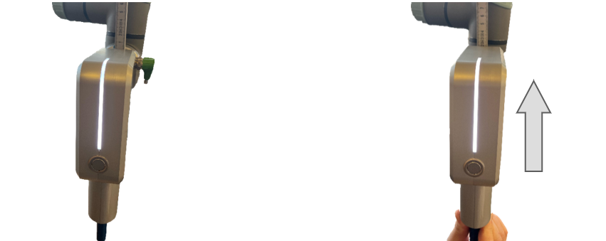
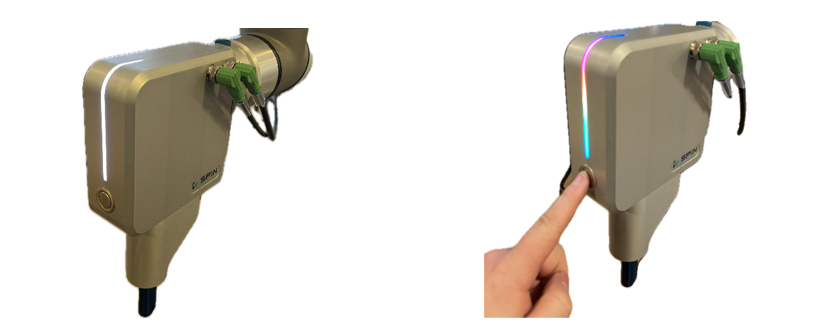
Ensure that robot is in a non-error state and the LED status on tool is white.
Check that the safety cable is connected from the SpinBridge to the robot control box.
Pull the tool up until the safety sensor is exposed and the LED status changes to red, triggering an emergency stop of the robot.
Check that the emergency stop of the robot was triggered correctly.
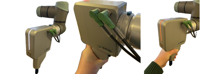
Ensure that robot is in a non-error state and the LED status on tool is white.
Press and hold the blue button on the back of the tool.
Ensure that the LED status changes to blue and that you can move the tool around.
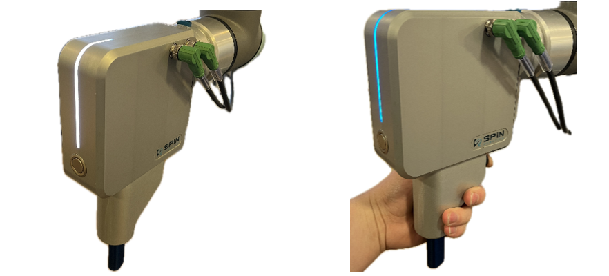
Press down on the blue tap and twist the tool counterclockwise to dismount it.
Tighten the bolt that connects the Spin Mount to the robot according to your robot manufacture’s specification.
Reattach the Spin Mount by aligning the left side groove of the robot side with the groove on the tool side. Twist the tool clockwise until the groove in the middle of the tap is aligned and the tool snaps into place.
Ensure that the tool is properly secured.